Radiographic testing (RT) is a non-destructive testing (NDT) method used to examine the test specimen’s volume and show the discontinuities and defects and their location inside the test specimen. This method uses X-rays and gamma rays to produce an image of the material being tested. The image, called a radiograph, shows any changes in thickness, internal or external defects, and other prominent details of the sample.
History of Radiography
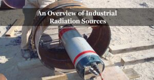
Radiographic testing mainly uses a beam of rays in examining the quality of the material. X-ray, the first-ever energy source for this method, was discovered in 1895 by a German scientist named Wilhelm Conrad Roentgen. He first observed a fluorescent glow from his cathode ray tube that can pass through heavy paper, casting shadows of solid objects.
This discovery led to the breakthrough of another form of penetrating rays in 1896, as French scientist Henri Becquerel discovered the natural radioactivity of fluorescent minerals, precisely uranium compounds. Same with the observations of Roentgen, these images of materials are produced once these are placed in between the radiation source and the photographic films. In 1898, Marie and Pierre Curie explored more of his work, intending to discover other elements, which gave rise to radium discovery. This became the initial industrial gamma-ray source after that. This was followed by discovering artificial gamma-ray sources that were stronger but less expensive than radium, such as cobalt and iridium.
Principle and Mechanism of Radiographic Testing
In this method, the material density and the differences in the thickness of the test specimen dictate the attenuation or the reduction of the detected penetrating radiation on the other side of the object, as there will be absorption or scattering of the rays.
The test specimen is placed between a radiation source and a film or detector (see the below figure). A beam of rays (either X-rays or gamma rays) will be emitted and allowed to penetrate through the material.

If the beam encounters a flaw, which usually has a lower density than the base material, then more than the expected amount of radiation will pass through the region and will be then recorded in the radiography film, which is placed on the opposite side of the test specimen. This area will be darker in the film, indicating that more radiation has been transmitted through the tested material. Varying degrees of black to white, termed film density, indicate the intensity of the beam’s penetration. Certified inspectors can then readily interpret the resulting radiograph and identify and locate the discontinuities and defects in the material.
X-Ray or Gamma Ray?
The radiographic testing method may be used for materials with a thickness that ranges from 6 – 230 millimeters. The thickness of the test specimen then dictates the type of radiation source that must be used in the RT method. The production of X-rays requires higher photon energies that range from 10 – 100 MeV (mega electron volt). Thus, it is preferably used for materials with thinner specifications and/or less density.
On the other hand, most industrial radiographic isotopes only need lower energy to penetrate materials, so these are usually used for thicker or denser materials. Iridium-192, with a half-life of 74 days, can pass through steel with a thickness of 6 – 75 mm with just 0.31 – 0.60 MeV; Cesium-137, with a half-life of 30.1 years, can penetrate steel with a thickness of 13 – 100 mm with just 0.66 MeV; lastly, Cobalt-60 with a half-life of 5.3 years, can traverse steel with a thickness of 19 – 230 mm with just 1.17 – 1.33 MeV.
Requirements for Radiographic Testing method
The radiographic testing method requires several materials, and its execution must be done with precautions since the radiations pose health risks once exposed to a high amount. The following must be obtained and noted before doing this method:
- Guides such as National Council on Radiation Protection and Measurements (NCRP) 147, 116, and 144 may be used to ensure safety and prevent examiners from receiving radiation dosages that are higher than usual.
- Radiographic exposure areas must be cleaned first for unaliased data and results.
- Darkroom facilities must have the capability to produce uniform radiographs. This will aid in preventing blemishes or artifacts on the produced images, ensuring the accurate interpretation of the area.
- The filming view area must not allow entry of other light to avoid reflective glare from the film’s surface.
- Films must be selected based on the energy level of the radiation source, thickness and configuration of the test specimen, and expected image quality. The class requirement may refer to American Society for Testing and Materials (ASTM) Test Method E1815 (Standard Test Method for Classification of Film Systems for Industrial Radiography).
- Film processing solutions are used to aid the production of consistent radiographs. ASTM Guide E999 (Standard Guide for Controlling the Quality of Industrial Radiographic Film Processing) may be consulted regarding film processing.
- Radiation sources are classified and identified by the appropriate X-ray voltage and current levels for the X-radiation and the type of isotopes for the gamma-ray, which are based on the material type and thickness of the test specimen and the length of exposure.
- Intensifying screens, such as lead foil, fluorescent, fluorometallic, and metallic screens, must be selected based on the penetrameter’s required voltage range and sensitivity.
- Other miscellaneous materials that are needed are non-film recording media (e. g., paper and analog tape), film holders, and cassettes.
Types and Techniques of Radiographic Testing method
Radiographic testing methods can be classified into two (2) types: conventional radiography and digital radiography.
Conventional radiography captures the image of the area being investigated using a highly sensitive radiographic film that reacts to the radiation that is emitted in the RT process. This leaves a permanent record of the examination, but the films can only be used once, and they take a while to be processed and interpreted.
On the other hand, digital radiography uses a digital detector instead of films to display the radiographic images. This is done instantaneously. Thus it offers a better lead time than that conventional radiography. Images produced through this method have higher quality and can reflect flaws sharply than the former method. There are four (4) techniques under this RT type:
- Computed radiography uses a phosphor imaging plate instead of a film. However, the reflected image on the phosphor plate is transmitted as a digital signal which then can be viewed on the computer screen. This is much faster than conventional radiography but the slowest among the digital radiography techniques.
- Similar to the computed radiography, direct radiography also uses a flat panel, which detects the image. However, this is almost instantaneous since it captures the image directly and then displays it immediately on the computer screen.
- Real-time radiography provides instantaneous radiographic images that are produced as the emitted radiation interacts with a phosphor screen or panel detector. These rays create a digital image that can be moved and analyzed at the same time instantaneously. However, the image from this technique has low contrast and quality when compared to conventional radiography.
- Computed tomography uses hundreds of thousands of two-dimensional prints of the scanned image, which are superimposed to produce a three-dimensional radiographic image that can be readily repositioned and analyzed. Either a moving detector with a stationary sample or vice versa is used to facilitate the imaging. This method is advantageous for samples with small and/or complex configurations. This limits human error, thus provides higher quality imaging. However, these advantages require longer rendering time, are expensive, and have larger data storage.
Read more: A Guide To Radiographic Films And Intensifying Screens.
Common uses of Radiographic Testing
Radiography Testing is a suitable nondestructive testing method for detecting surface and subsurface discontinuities such as cracks, porosity, inclusions, and voids in the test piece. This is usually used in quality testing and verification of castings, forgings, and weldments.
Advantages and disadvantages of Radiographic Testing
The features of RT testing method are as follow:
- RT may be used in both metallic and non-metallic materials.
- Surface and subsurface flaws can be easily detected using this method.
- It permits inspection at the volumetric level, meaning it can evaluate through the insides of the test specimen.
- Photographic and visual graphs can be stored and kept permanently as test records for future references.
However, there are also several drawbacks of using this method, which are:
- Its execution requires bulky and heavy equipment. However, new technologies made portable systems for use in the field and elevated positions possible. Still, there might be a compromise in the quality of the imaging.
- This equipment can also be expensive due to the method requirements.
- Both sides of the specimen must be readily accessible.
- The configuration of the material (e. g., position of the joints, corners, etc.) may affect the applicability of the method, as the orientation of the feature may result in multiple interpretations as reflected in the image.
- The use of X-rays and gamma rays may pose health risks at higher dosages.
References:
- McEvily, A., 2013. Metal Failures: Mechanisms, Analysis, Prevention. Hoboken, N.J.: John Wiley & Sons, Inc.
- ASTM E1742 / E1742M-18, Standard Practice for Radiographic Examination, ASTM International, West Conshohocken, PA, 2018.