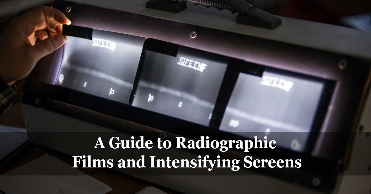
Radiographic films are the permanent record where the test result from the radiography test is recorded. The radiographic film provides a permanent visible image of the shadow resulting from the penetrating radiation.
The radiography test results are typically recorded on radiographic film, radiographic paper, or electrostatically sensitive paper that is commonly used in the xeroradiography process.
Radiographic films are generally classified according to the various use purposes involved; the films’ classification is based on the film features, speed, contrast, and application.
Structure of Industrial Radiographic Films
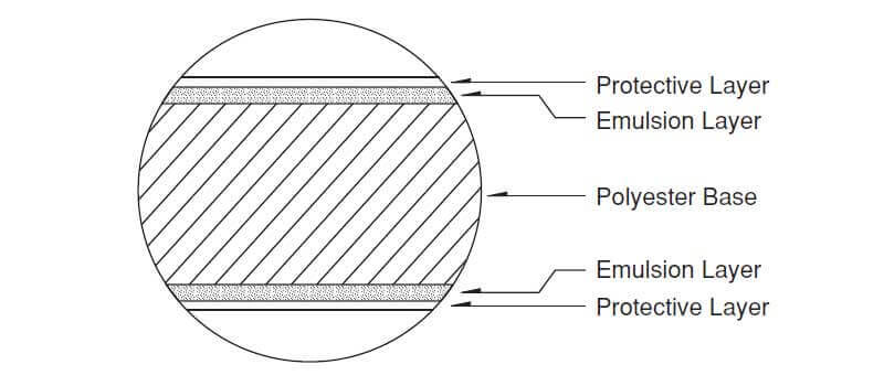
Radiographic films consist of two emulsions, one on both sides of the film base. The emulsion is coated in layers; a thin outer protective layer is added to both sides of the emulsion layer to protect it.
The film comprises seven layers; the base is usually tinted blue and is made from cellulose, triacetate, or polyester, which is about 0.175 mm thick. Both sides of the base have a very thin layer of adhesive, adhering to the adhesive layers of emulsion, which is about 0.01~0.015 mm thick. The emulsion contains many small silver halide crystals as the photosensitive material; the silver halide crystals are suspended in gelatin. A very thin (about 0.01 mm thick) but a tough coating of gelatin called a protective overcoat covers the emulsion to protect it against minor abrasion. The radiographic film’s total thickness is approximately 0.2~0.21 mm, including film base, two emulsions, two adhesive undercoats, and two protective overcoats.
The silver halides in the emulsion layers form an image when influenced by radiation, electrons, or fluorescent light. The two emulsion layers increase the absorption of the highly-penetrative radiation. The photosensitive silver compound is utilized more effectively; thus, the two emulsion layers increase the contrast and image density of the radiographs.
The difference between general photographic film and industrial radiography is that the general photography film emulsion layer is coated only on one side of the base. In contrast, it is coated on both sides in the industrial radiographic film.
The exposed film must be chemically processed to produce a visible image. The film is treated with a developer, and a chemical reaction occurs, which converts the exposed silver halide grains in the latent image into black metallic silver. The metallic silver remains suspended in the gelatin, creating blackening or shades of gray in the developed image and making it visible. The film is then treated with a fixer, which converts unexposed silver halide grains into a water-soluble compound. The residue from the development and fixing are washed off, followed by drying the film and making it ready for the next evaluation and interpretation process.
Classification of Radiographic Films
Various international standards classify radiographic films; European and American standards are the most common standards for classifying radiographic films. The classification is based on the applications and features of each type. Radiographic film manufacturers such as Fuji and AGFA tend to provide a unique product code for their products; however, each product group can be linked with the standard classes.
The most common international standards classifying radiographic films are:
- ASTM E1815 – Standard Test Method for Classification of Film Systems for Industrial Radiography.
- ISO 11699-1 – Non-destructive testing — Industrial radiographic film — Part 1: Classification of film systems for industrial radiography.
As per ASTM E1815 standard, there are six general classifications of the industrial radiographic film: Special, Class I, Class II, Class II, Class W-A, and Class W-B.
Class “Special”
Finest grain high contrast films, Class “special” film has the maximum sharpness and differentiation characteristics. It is suitable for new materials, such as carbon fiber reinforced plastics and ceramic products.
They are typically used for microelectronic parts and castings (low to medium atomic number metals).
Class I
An ultra-fine grain high contrast films, Class I films have excellent sharpness and high differentiation characteristics. It is suitable for the inspection of low atomic number materials where fine image detail is imperative with low kilo-voltage x-ray sources and inspection of higher atomic number materials with high kilo-voltage x-ray or gamma-ray sources.
They are typically used for electronic parts, welds (low to medium atomic number metals), and graphite-epoxy composites.
Class II
A very fine grain high contrast film, Class II films, are suitable for inspecting light metals with low activity radiation sources and inspection of thick, higher density parts with high kilo-voltage x-ray or gamma-ray sources.
They are typically used for welds (medium to higher atomic no. metals) and castings (medium to higher atomic no. metals).
Class III
A high-speed fine grain high contrast film, Class III films, are suitable for inspecting a wide range of products with low-to-high kilo-voltage x-ray and gamma-ray sources. Class III films are useful when gamma-ray sources of high activity are unavailable or when very thick components are to be inspected. It is also useful in x-ray diffraction work.
They are typically used for heavy and multi-thick steel parts.
Class W-A
An ultra-fine grain medium-high contrast film, Class W-A films, are suitable for inspecting a wide range of thickness parts such as precision cast parts with X-ray or gamma-ray sources.
They are typically used for castings and other multi-thickness parts.
Class W-B
An extremely fine grain medium contrast film, Class W-B films, are suitable for inspecting multi-thick, low-atomic number metal, and steel cast parts.
They are typically used for castings and other multi-thickness parts.
What is Radiographic Intensifying Screens?
During radiographic image formation resulting from the strike of the radiography radiation beam to the film, approximately 1% only of the radiation energy is absorbed to form the radiographic image, while 99% of the remaining energy is not useful in the photographic work and passes through the film.
Due to the minor amount of the absorbed radiation, full utilization of the available radiation energy is necessary. Therefore, intensifying screens come into the picture. The intensifying screen is a thin sheet or layer consisting of material that emits less penetrating secondary electrons in fluorescent light form when struck by the radiation, causing the film to expose. The common types of industrial intensifying screens are lead screens, fluorescent screens, and fluorometallic screens.
The film is placed between two sheets of the intensifying screens; by intensifying the radiation, the film exposure time is reduced. The comparison between radiation-intensifying effects with the exposures made with intensifying screens to exposures made without intensifying screens is called the intensification factor.
Types of Radiographic Intensifying Screens
As previously discussed, the common types of industrial intensifying screens are lead screens, fluorescent screens, and fluorometallic screens.
Lead screens
The radiographic film is placed between two lead screens (front and back screens) made up of a homogeneous sheet of lead foil; the radiation affects the lead screen causing it to emit electrons (electrons are called secondary electrons) to which the film is sensitive, and intensifying effect occurs. The lead screen intensification method is used with either X-ray or gamma-radiation.
The thickness of the lead foil is 0.02 to 1.0 mm, the thickness of the lead screen is typically selected based on the radiation energy. The lead screen surface is usually polished for better contact with the film’s surface; besides, the screen should be free from any surface defects such as scratches or cracks, which in case of presence, will transfer in the radiograph image.
The lead screens are usually used for an x-ray energy range of 80 keV to 420 keV or gamma-ray of equal energy, such as produced by Iridium192. However, lead material is not the best to use for intensifying screens whenever high-energy radiation is required. High-energy radiation such as produced by Cobalt60 or megavoltage X-rays in the energy range 5-8 MeV, screens made up of copper or steel material have proven to produce better quality radiographs than lead screens.
In general, lead screens improve the radiographic image’s contrast and reduce scatter, which gives better visual image details. The intensification factor of lead screens is usually from 2 to 3.
Fluorescent screens
Fluorescence means the material characteristic to instantly emit light under the influence of electromagnetic radiation; once the radiation source is removed or shut down, the lighting effect stops. The fluorescence phenomenon is utilized in film-based radiography.
The fluorescent screens are made up of a thin base layer; the layer is coated with a layer of micro-crystals of metallic salt (usually calcium tungstate), which demonstrate fluorescence characteristics.
When the screen is subjected to radiation, the screen’s fluorescence characteristic makes it fluoresce and light up. The light intensity varies based on the radiation intensity, and a very high intensification factor can be achieved that may significantly reduce the exposure time.
The film image produced by fluorescent screens has increased image unsharpness, resulting in a poor quality film image. Therefore, the industrial application of fluorescent screens is limited; the screens are only used whenever a drastic reduction of exposure time is required to detect large defects only. The intensification factor of fluorescent screens is usually from 10 to 200.
Fluorometallic screens
The fluorometallic screens are almost intermediate in nature between the lead screen and the fluorescent screen, which to a certain extent combine the advantages of both. The screens consist of two layers, each layer is made up of a lead foil coated with a fluorescent layer, and the film is placed between the two layers. The fluorometallic screens have a shorter life than the lead screens.
The intensification degree of fluorometallic screens mainly depends on the radiographic film’s spectral sensitivity for the light emitted by the screens. The intensification factor of fluorometallic screens is usually from 5 to 150.
In general, fluorometallic screens provide intermediate contrast of the radiographic image with considerable exposure time reduction.
Read more: An Overview Of Industrial Radiation Sources.
References:
- ASM Metals Handbook Volume 17, Nondestructive Evaluation and Quality Control.
- Kodak, Radiography in Modern Industry.
- GE – Inspection Technologies – Industrial Radiography – Image forming techniques.


