The image quality indicators (IQIs), which are also referred to as penetrameters, are test pieces used to control a radiograph’s quality. IQI indicates the contrast sensitivity and definition of the radiograph and serves the purpose of product testing. The sensitivity of an industrial radiograph is determined by using one or more image quality indicators.
The selection of Image quality indicators is made from either the same radiographed workpiece alloy material group or an alloy material group or grade with less radiation absorption than the material being radiographed. IQIs are used when the internal conditions of a specimen are to be examined in precise detail to aid in interpreting the radiographs.
Types of image quality indicator
The image quality indicator is categorized by either a hole-type IQI containing three different sized holes or a wire-type IQI containing six different sized wires. Image quality indicators are available in standard sizes of plate or wire in incremental thickness to cover most possibilities by overlapping the thickness of the material being radiographed. Their composition covers the majority of materials used in construction and industrial applications.
Image quality indicator materials are typically selected from the same material group as the workpiece to be radiographed. Materials are often grouped by their absorption level, for example, from Group I for lighter materials to Group V for heavy metals.
The standard image quality indicators are wire and hole types; we will discuss both types in more details as follow:
1. Hole-Type image quality indicator
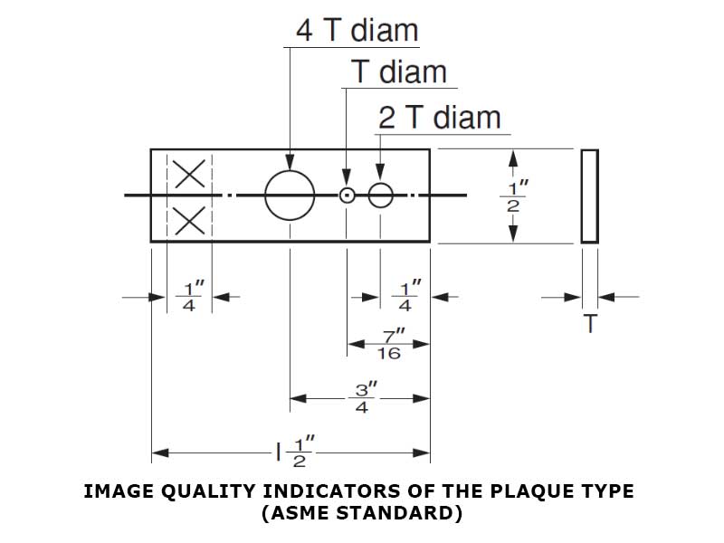
Hole-type image quality indicators are relatively thin pieces of material with radiation absorption characteristics similar to the workpiece to be radiographed. Hole-type IQI contains holes with diameters that are 1, 2, and 4 times its thickness. The following is the illustration of a hole-type IQI:
A two-part expression (A−BT) designate the quality level required for a radiograph:
- “A” is the maximum thickness permitted for the IQI; the thickness is determined as a percentage of the thickness of the workpiece.
- “B” is the diameter of the hole as a multiple of the thickness.
- “T” is the thickness.
A quality level of 2-2T is adequate for most radiographic testing industrial applications. A 2-2T IQI means that it has a thickness of 2% of the material thickness and that a hole that is twice the IQI thickness must be detectable on the radiograph. This presentation verifies that the radiographic technique can show a material loss of 2% in the area of interest.
2. Wire-Type image quality indicator
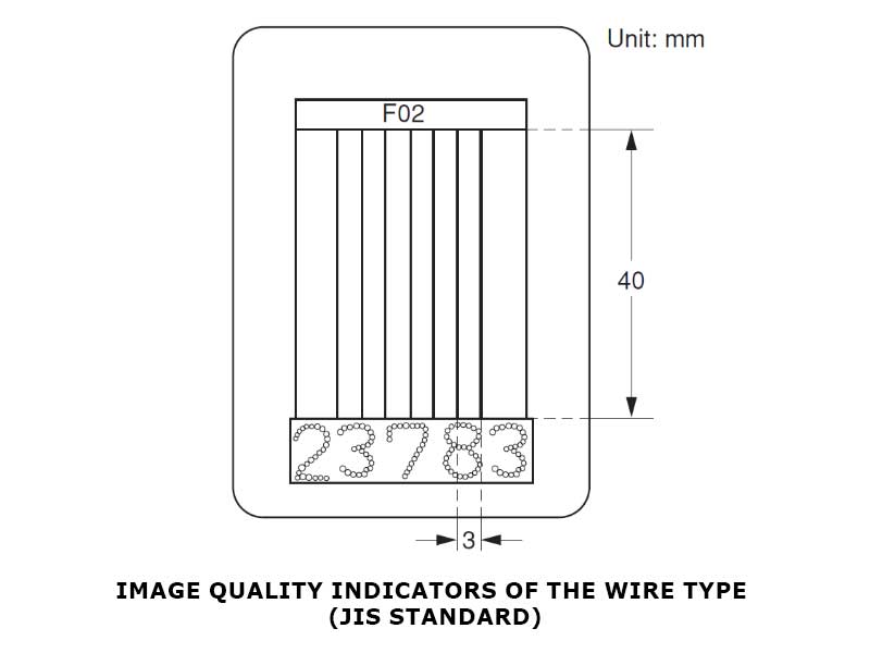
Wire image quality indicators consist of a set of six wires; the wires are arranged in order of incremental diameter and encased between two sheets of clear plastic. The same image quality levels and expressions used for hole-type image quality indicators are typically used for wire-type. The following is the illustration of a wire-type IQI:
Radiograph film acceptance criteria
A radiograph is considered acceptable if the entire outline of the IQI is visible, the hole or wires are discernable, and the density of the film is within the required range.
The radiograph film image quality is expressed in terms of IQI thickness or diameter of the visible wire for wire type IQI. The typical industrial requirement for radiography sensitivity level is ‘2-2T’. The first (2) indicates that the image quality indicator thickness is 2% of the workpiece thickness, or the wire diameter 2% of the workpiece thickness (in the case of wire type IQI). The second part (2T) on the plate type IQI indicates that the hole size visible on the radiograph is twice the thickness of the IQI plaque. The sensitivity of the radiograph increases as the number is lowered.
Radiographic density, film density is a measure of the darkness of the film after exposure and processing. The density value works as follow:
- A density of zero means it is a transparent film.
- A density of 1.0 permits 10 % of incident light to pass through the film.
- A density of 2.0 permits 1 %.
- A density of 3.0 permits 0.1 %.
- A density of 4.0 permits 0.01 %.
The required film density as per the codes are:
- 8–4.0 for X-ray.
- 0–4.0 for gamma-ray.
Related Article: A Guide To Radiographic Films And Intensifying Screens.
Placement of image quality indicator
For achieving the best result, the image quality indicator should be placed on the source side of the part being examined at the nearest possible point from the radiation source. Whenever setting the IQI from the source side is not possible due to inaccessibility or any other reason, a lead letter ‘F’ has to be placed on or adjacent to the IQI to indicate on the film that the IQI was placed on the film side.
When performing a radiographic test for a welding joint, the hole type IQIs are typically placed adjacent to or on the weld joint. Wire IQIs are placed on the weld with the length of the IQI wires perpendicular to the weld’s length. When placing the IQI, the identification numbers must not be in the area of interest, except where the geometric configuration of the component makes it impractical.
References:
- Clifford Matthews, in A Quick Guide to API 510 Certified Pressure Vessel Inspector Syllabus, 2010.
- Clifford Matthews, in A Quick Guide to API 570 Certified Pipework Inspector Syllabus, 2009.
- Applied Welding Engineering Book, Processes, Codes, and Standards.


