Ultrasonic Testing (UT) is a non-destructive testing (NDT) method that utilizes the propagation of high-frequency sound waves or ultrasonic waves. These waves are then recorded using an ultrasonic transducer, and any attendant losses in the energy received back by the transducer indicate the presence of the defects on the object being inspected. Mainly, this method is best used to detect flaws since it has high sensitivity and penetrating power. The presence, distance, and location of the flaws can be easily concluded using this approach.
History of the Ultrasonic Testing
In 1928, Soviet Scientist Sergei Y. Sokolov, the father of modern UT, originally demonstrated the use of ultrasonic in flaw detection in metals. Following this, British scientist Donald Sproule then used the concept of echo-sounding for defect detection in steel using separate transmitting and receiving transducers. This led to the introduction of Firestone’s ‘Supersonic Reflectoscope’ in 1945, and from there, it became the first ultrasonic flaw detector that was offered commercially.
From the bulky vacuum tubes that require a lot of energy, the development of solid-state circuitry has steered the rise of smaller, battery-operated instruments that are also portable for field applications. Over the years and progressive process improvement, the development of the digital instruments used today continued, providing better operational functionalities of the equipment such as stable calibration, precise measurements, and data retention capabilities.
Principle and Mechanism of Ultrasonic Testing
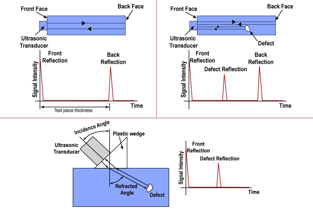
Ultrasonic testing is usually done using the technique called pulse-echo, wherein a piezoelectric transducer, when wetted with a couplant, is used to introduce a pulse of sound waves into the specimen. This transducer is an anisotropic crystal that can either convert the deformation of the crystal into a voltage or transform an external voltage into the vibration of the crystal. Then, the pulse of sound waves is allowed to travel all through the specimen.
Upon reaching the end of the material, the wave is expected to be reflected the side of the source. This end may be the back face of the object or any discontinuity. The sound waves are presented using an oscilloscope presentation which relates the distance and time traveled by the pulse of the sound. A frequency range of 0.5 to 10 MHz, which is above the limit of human hearing of 20,000 kHz, is usually used in this method.
Requirements for performing Ultrasonic Testing
In the execution of the Ultrasonic testing, a couplant is used to patch up the space between the transducer and the specimen to guarantee effective sound transmission by creating an acoustic impedance between the transducer and the test material. Without the couplant, there will be a presence of thin air in between the specimen and the transducer even though they are in direct contact, and just a very small amount of energy will be transferred, making the method less accurate. The application of couplant excludes all air in between the surfaces and smooths out the irregularities on the surface.
Aside from the couplant, the following are also required in the execution of the Ultrasonic testing method:
- The technical person to perform the testing must be qualified in accordance with American National Standards Institute/American Society for Nondestructive Testing Certification of Personnel (ANST/ASNT CP) 189 or National Aerospace Standard (NAS) 410, and be an approved NDT Level III in the practice of UT.
- Calibrated electronic equipment with appropriate search units with attenuators, decade switches, alarms, voltage regulators is needed.
- Manipulating equipment is needed to support the adjustments of the search unit if needed.
Techniques of Ultrasonic Testing methods
Two methods are usually implemented in using a couplant:
- Immersion method.
- Contact method.
In immersion testing, a combination of clean, deaerated water and a wetting and/or corrosion inhibiting agent is used as a couplant. The specimen is then immersed into this liquid contained in a tank or water column. The water must be free from bubbles and other materials that might interfere with the testing.
On the other hand, contact testing involves using a thin liquid or semi-liquid film as a couplant, as the transducer is held directly on the object being tested. This couplant is usually a grease-like material that fully coats the surface of the transducer and the specimen.
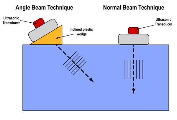
Three techniques are used in contact testing, as determined by the type of sound waves used in each method: the normal beam, angle beam I, and angle beam II.
- In the normal beam technique (also known as longitudinal, compression, or straight beam), the ultrasonic pulse is projected into the test piece normally or perpendicular to the surface of the test specimen. This may be done using the transmission technique in which a detector is placed on the back face of the test specimen; or pulse-echo technique, in which either a single transducer (used in both sending and receiving signals) or two transducers (one for sending the signal and the other to receive the reflected signals).
- In general, the angle beam technique is used in detecting cracks at a predetermined angle. The sound is then transmitted into the material with the transducer mounted on an inclined plastic wedge. Snell’s law, which relates the angles of the incidence and refraction beams, is used to interpret the data received from this technique. Depending on the angle of incidence, two modes may be obtained:
-
- Angle beam I result in shear waves when the angle of incidence is initially increased further.
- Angle beam II gives rise to surface waves due to a further increase of the angle of incidence that weakens the shear waves, turning them into the aforementioned wave.
-
Types of Ultrasonic Testing methods
Three types of scan modes are used in Ultrasonic testing, depending on the information needed to be obtained:
- A-Scan mode is the most widely used, which shows a quantitative display of signal intensity or the size of the flaw. As a result, the time of flight, which indicates the depth of the flaw, is obtained at one point on the object’s surface. This uses a fixed transducer and is beneficial if the information about the flaw type, depth, and location is needed to be obtained.
- B-scan mode is the quantitative display of time of flight along a line on the surface. In this scan, the transducer and the specimen move with respect to each other. The size, however, only in one direction, the position, and depth up to a certain degree the shape and orientation of the internal flaws can be derived from this model.
- C-Scan mode is a two-dimensional semiquantitative display of the echo intensity of a test piece. It reveals the plane section of a test piece but provides no depth or orientation information. Also, the entire surface scanned is raster or traversed.
Common uses and limitations of Ultrasonic Testing
Compared to the other NDT methods, Ultrasonic testing (UT) gives greater accuracy in determining the depth of internal flaws and the thickness of parallel surfaces. Furthermore, this method may be used to inspect a wide range of materials, from steel, alloys, and metals, to woods, composites, and concretes. However, since this is highly dependent on the sound transmissibility and signal noise capacity of the material, its accuracy is affected by such properties of the materials.
Materials with low sound transmissibility and high signal noise, such as cast iron and other coarse-grained materials, can result in inaccurate and ineffective inspection using this method. The orientation of the flaws also affects the correctness of this technique. In this case, the sound waves must not be entirely parallel with the direction of the linear flaws for the attenuation of waves to occur and to be detected by the transducer.
Advantages and disadvantages of Ultrasonic Testing
Ultrasonic testing offers the following advantages:
- It presents immediate results in both portable and highly automated operations.
- It operates with high penetrating power and sensitivity, which permits detecting deep and extremely small flaws. Ranges include surface and subsurface defects.
- Unlike radiographic testing, UT only requires at least one accessible surface.
- Aside from the depth and thickness of the flaws, it can also estimate the defects’ size, orientation, shape, and nature.
- It can also identify and estimate the structure of alloys of the material depending on the differences in the object’s acoustic properties.
- It does not pose operational hazards since no chemicals and such are needed to execute the testing.
On the other hand, this method also has downsides, such as:
- The results of this method are operator-dependent. The training required for the operator is more extensive than what is usually needed for the other methods. Instances such as manual operation and development of inspection procedures require extensive technical knowledge.
- Inspection of components that have irregular shape, evident roughness, smaller size and/or thickness, and inconsistent homogeneity is deemed difficult.
- Thorough cleaning must be done on the surface.
- The use of couplant is necessary to effectively transfer the ultrasonic wave energy between the transducers and the components under investigation.
Related article: Non-Destructive Testing (NDT) – Insider’s Guide.
Related article: Radiographic Testing (RT) – Insider’s Overview.
References:
- McEvily, A., 2013. Metal Failures: Mechanisms, Analysis, Prevention. Hoboken, N.J.: John Wiley & Sons, Inc.
- ASTM E2375-08, Standard Practice for Ultrasonic Testing of Wrought Products, ASTM International, West Conshohocken, PA, 2008.

