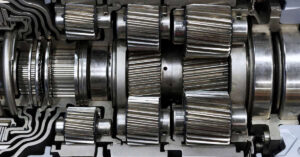
Shaft couplings are essential components for various machines and mechanisms used in engineering, automotive mechanics, and many other fields. These couplings work to connect two shafts together securely and accurately while allowing them to move or rotate independently without getting damaged.
To ensure the highest level of reliability, you must choose the right type of coupling for your specific application. In this article, we will provide an informative guide on what shaft coupling is, its function, and the different types of shaft couplings – from rigid types to flexible ones, as well as hydraulic or fluid models – so that you can make the best choice for your project! Keep reading to learn more!
What is a shaft coupling, and what is its function?
You can define it as a mechanical component that couples two rotating shafts, a driver (an electric motor or internal combustion engine) and a driven (a water pump or a generator), and the purpose is to transmit power from the driveshaft to the driven shaft.
Based on application, this mechanical device could be of two types; rigid or flexible, and this is dependent on the alignment accuracies and torque requirements of the system.
The driver and driven shafts do not need to be of the same diameter; however, in most cases, they rotate on the same axes. They can be used even when the axes of the driver and driven shaft axes are not the same.
Its Uses and functions include:
- To hold the driver and driven shafts in good alignment, easy to assemble and disassemble and transmit the power efficiently, with minimum losses.
- To minimize transmission of shock loads between the driver and driven shafts and protect against overload.
- To provide mechanical flexibility (reduces bearing wear, vibration, etc.).
- To couple two units manufactured separately, viz. an electric motor and a water pump, an internal combustion engine, a water pump or a generator, etc.
- Many times the construction material of the driven shaft needs to be hygienic (stainless steel) for the machinery used in the dairy, food industry, etc. Shaft coupling is an ideal option in such situations since you cannot use a nonmagnetic stainless steel shaft for the electric motor.
- Flexible couplings allow slight misalignment (axial, angular, and parallel).
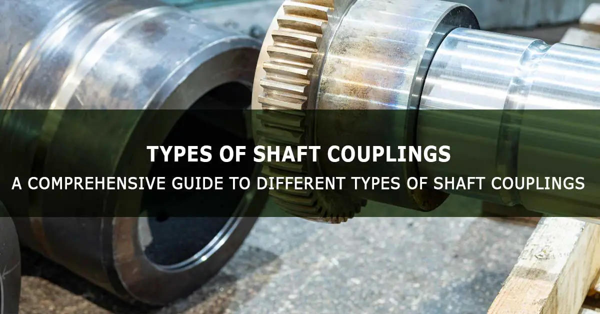
Different types of shaft couplings
There are three types of shaft couplings:
- Rigid shaft coupling.
- Flexible shaft coupling.
- Fluid or hydraulic coupling
Rigid Shaft Couplings
This mechanical component joins a perfectly aligned driver and driven shafts. As the name indicates, this form of shaft coupling has a low misalignment tolerance. It cannot accommodate minor misalignments between the driver and the driven shafts, hence the need for regular lubrication.
Flexible Shaft Couplings
Flexible couplings accommodate slight shaft misalignment between the driver and driven shafts (axial, angular, and parallel). They are flexible due to the flexing of thin metallic discs.
A flexible coupling, apart from joining the driver and driven shaft, keeps them always aligned. Few flexible shaft couplings can work without periodic lubrication.
Fluid or Hydraulic Shaft Couplings
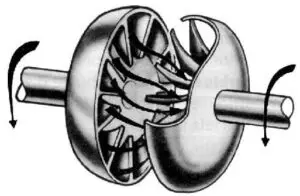
A fluid coupling is a hydrodynamic device that transmits mechanical power from a driving impeller to a driven impeller or runner by accelerating and decelerating the hydraulic fluid.
Types of Rigid Shaft Couplings
Different types of rigid coupling are:
- Sleeve or muff coupling
- Split muff or compression coupling.
- Flange coupling.
Sleeve or Muff Shaft Couplings
Sleeve coupling is a simple type of rigid coupling. It consists of driver and driven shafts (same diameter) components with the same size keyways, a sleeve or muff with an internal diameter, an internal keyway matching the driver and driven shafts, and a gib-head key.
In operation, the sleeve is assembled on the driver and the driven shaft, and the shafts are locked together with the single gib-key. The torque transmission occurs due to the rigid assembly between the two shafts. All the connected parts must be able to take the transmission load.
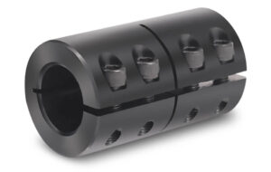
Split Muff or Compression Shaft Couplings
The split muff coupling consists of driver and driven shafts (same diameter) with the same size keyways, split muffs that can be assembled on the two shafts (with four screws and locknuts), and a gib-head key.
When assembled, the split muff becomes a sleeve with a bore and keyway matching the shafts. The split muff coupling is assembled on the two shafts, and the gib-key is pushed to lock the shafts with the split muffs.
This method ensures the power from the driveshaft to the driven shaft due to the key that locks both the shafts together and the friction between the muff and the shafts. And this is also used for transmitting higher speeds.
Flange Couplings
This coupling is of three types; unprotected, protected, and marine type. The general construction of all three types of flange couplings is similar, and it consists of two hub flanges assembled on the driver and driven shafts with keys (in the case of marine type, the flanges are integral with the shafts), and bolts and nuts for bolting the two flanges together.
One of the flanges has a projection or step diameter on its face, and the other has a matching recess. This enables proper alignment and is also suitable for transmitting heavy loads.
The difference between the three types of flange coupling:
- The unprotected type flange coupling does not protect the bolt and nut heads.
- The protected type flange coupling has a collar on the outer face of the flanges to protect the bolt and nut heads.
- The marine-type flange coupling has flanges integral to the driver and driven shafts.
Types of Flexible Shaft Couplings
Different types of flexible couplings are:
- Bushed pin-type coupling.
- Oldham coupling.
- Universal coupling.
- Gear coupling.
- Bellow coupling.
- Jaw couplings.
- Diaphragm couplings.
- Disc coupling.
- Tire coupling.
- Roller chain coupling.
Bushed pin-type couplings
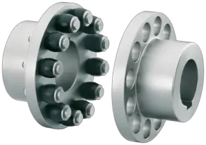
This type looks like a rigid flange coupling. But, unlike in a flanged coupling, the two flanged hubs mounted on the driver and driven shafts and keyed to them are dissimilar.
The flanged hub on the driver shaft has its bolting holes fitted with a set of brass and rubber bushes (a rubber bush fits in the bolting hole with a brass bush in it), which protrudes beyond the flanged hub’s interface. The clamping bolts pass through the set of bushes and clamp the other flanged hub with locknuts.
There is an approximate clearance of 5 mm between the two inner faces of the hubs (due to the protruded bushes). The driver and the driven hub flanges have no rigid connection, and the drive is transmitted through the bolt/pin in the set of bushes. The rubber bushes allow slight axial misalignment as well as angular misalignment).
Oldham couplings
Oldham couplings join two shafts whose axes are parallel to each other in the same plane (lateral misalignment). This component consists of two hub flanges, each fitted on the driver and the driven shaft with keys and an intermediate flange.
The hub flanges have a slot on their faces positioned 90 degrees to each other. The intermediate piece has two tongues matching with the slots on the driver and driven hub flanges. The floating intermediate flange (sandwiched between the driver and driven hub flanges) transmits the power during operation.
Universal couplings
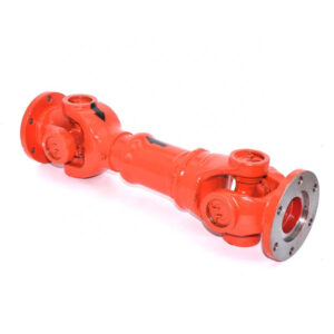
The universal or Hooke’s coupling connects two shafts that are inclined to each other by a small angle, and this is so flexible that it allows the angle of inclination to vary within a limit.
One popular use of these types of couplings is to transmit the drive from the gearbox shaft of an automobile to the shaft that drives the differential gears on the rear or front axle. Universal couplings are also used in a multi-spindle drilling machine. This type of coupling is good for transmitting higher torque capacities.
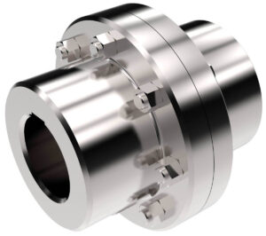
Gear couplings
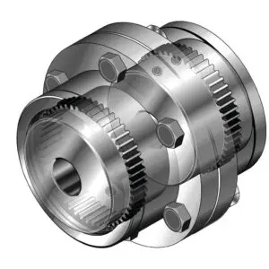
You can call this type an improved version of the flange coupling. In this type, the flange and hub on the driver and driven side are separate parts. The hub has external gear teeth, and the flange has internal gear that matches the crown gear. The hubs are assembled to the driver and driven shafts with keys, and the flanges are assembled onto the hubs.
The driver and driven side flanges are assembled with bolts and nuts. The assembly has seal rings and lubrication points. Gear coupling can accommodate slight misalignment between the two shafts (up to 2º in angular and up to 0.02ʺ mm lateral). And this is useful for transmitting higher torque capacity due to the presence of matching gears that provide a positive drive.
Bellows couplings
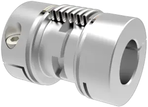
Bellows coupling is generally made from stainless steel metal. It has metal bellows in the center width and has a split hub on either side to connect to the driver and the driven shafts. The split hubs have provision for closing the slit by a screw so that they get assembled with the shaft.
This device is good for high-speed, high-torque capability and has good torsional rigidity. They are also suitable for motion control applications. The thin-walled bellows can accommodate slight angular and axial misalignments.
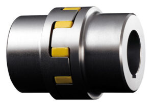
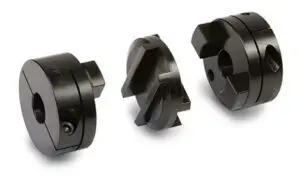
Jaw couplings
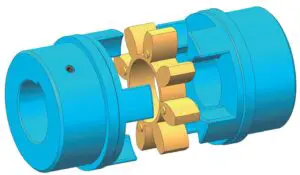
Curved and Straight Jaw couplings are general-purpose couplings for power transmission and can accommodate slight misalignment and reduce vibrations. The simple construction consists of two hubs with jaws and an Elastoplast intermediate piece called a spider.
Normally the two hubs can be bored (internal turning) to match the driver and driven shafts and assembled on the shaft using a key or grub screw. The spider is sandwiched between the jaws of the driver and driven hubs and transmits the drive. The driver and the driven hubs do not have face-to-face metal contact.
Diaphragm couplings
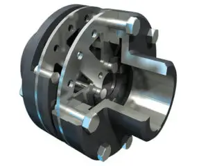
This type is a non-lubricated type of flexible coupling and is useful for transmitting high torques and high speeds like in turbomachinery. The diaphragm (flexible member) can be of one metal plate or a series of plates.
The torque is transmitted from the outside diameter of the flexible metal diaphragm to the inside diameter, across the spacer hub, and then from the inside diameter of the flexible diaphragm to the outer diameter and the driven hub.
A double flexible diaphragm coupling (with a central flanged spacer hub) can accommodate slight angular, axial, and parallel misalignment between the driver and the driven shafts.
Disc couplings
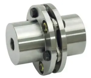
This mechanical device consists of two hubs (assembled on the driver and driven shaft with keys), a spacer with a flange on both ends, two-disc packs, and a set of disc packs that bolts to the shaft hubs. The two hub flanges, the disc packs, and the spacer flanges have holes for bolting on a common bolt circle.
The torque is transmitted through the flexible disc packs. A joining with two disc packs can accommodate slight axial, angular, and parallel misalignment, while one with a single disc pack can accommodate only slight axial and angular misalignment. This type is suitable for transmitting torque between two shafts supported with bearings.
Tire couplings
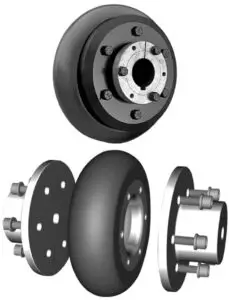
This type has a simple construction: a rubber or polyurethane tire connecting the two hubs fitted on the driver and driven shafts. Power transmission is through the rubber tire, hence the flexibility to accommodate misalignment and shock loads.
Roller chain couplings
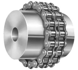
This type consists of two hubs (connected to the driver and driven shafts), each with a radial sprocket. The two sprockets are connected or engaged with one double-pitch roller chain.
The common double chain facilitates torque transmission, and the chain clearance accommodates slight angular, axial, and parallel misalignment between the driver and driven shafts. This type suits low and moderate speed and torque applications and needs regular lubrication.
Fluid or hydraulic couplings
What happens if you keep an idle fan in front of an electric fan blowing air? The answer is the idle fan starts turning. If you run in the open-air holding a paper fan, the paper fan starts turning. This principle is made use of in a fluid or hydraulic coupling.
A fluid coupling is a hydrodynamic device that transmits mechanical power from a driving impeller to a driven impeller or runner by accelerating and decelerating the hydraulic fluid. The fluid coupling consists of an impeller on the driving shaft and the driven shaft with a runner on it, and the impeller and the runner are placed in a sealed chamber filled with hydraulic fluid.
As the impeller starts rotating, it throws out the fluid at high velocity. The fluid at high velocity makes the runner on the driven shaft rotate, and this is how the torque is transmitted from the driver (impeller) shaft to the driven (runner) shaft. The same concept to mechanical turbines.
Many machines need the drive to start at zero velocity, and the full speed is reached smoothly with step-less increments. Hydraulic coupling can meet such requirements by controlling the speed of the driver (impeller) shaft. The hydraulic coupling can be of constant speed type or variable speed type.
Conclusion
Shaft couplings are an essential component of many mechanisms and have wide applications across many industries, providing reliable connections while allowing for independent movement and rotation.
Different types of shaft couplings exist that vary in rigidity, flexibility, and fluid – each with unique advantages, making them suitable for specific applications.
We hope this guide has given you the information you need to make the best choice for your project!
References