Have you ever thought about what revs up your car, motorcycle, or heavy-duty industrial machinery at work? That’s right! It’s the good old gearbox playing the unsung hero behind the scenes. But what exactly is a gearbox, and why is it indispensable?
A gearbox, in essence, acts as the middleman, catching the baton from the prime mover (may it be an electric motor or an internal combustion engine) and passing it on to the driven shaft – a propeller shaft of a vehicle or an industrial machine’s spindle. Its stealthy yet remarkable role breathes life into the machines by deftly manipulating a set of gears, transforming the input drive into high output torque or speed, and finally introducing it to the driven shaft.
We will embark on an enlightening journey, enriching your gearbox knowledge base. This exploration will dive into the symbiotic relationship between torque and speed, provide a more comprehensive understanding of what a gearbox is and why we can’t do without one, and finally, unravel the intriguing variety of gearboxes and their practical applications.
What Is the Relationship between Torque and Speed?
Have you ever wondered about the phenomena of torque and speed and their connectivity? When maintaining a steady drive at the input of a gearbox, an intriguing inverse proportionality between torque and speed surfaces—increasing torque reduces speed, and the converse also stands true.
For example, when inching uphill, your vehicle sustains a lower speed as it needs increased torque to ascend. Likewise, when cruising on a flat, even road, the need for torque is less, enabling medium or high speeds.
Teethed gears transmit rotary motion from one to another in a close-knit mesh arrangement. Consider two gears, Gear 1 (having 60 teeth) and Gear 2 (with 10 teeth). When Gear 1 drives Gear 2, with every revolution of Gear 1, Gear 2 will spin six times, a mechanism employed to amplify speed. Flip the situation—Gear 2 becomes the driver and Gear 1, the driven—every six revolutions of Gear 2 result in one revolution by Gear 1. Here, the speed decreases, but it leads to a torque surge.
What Is a Gearbox? Why Is a Gearbox Required?
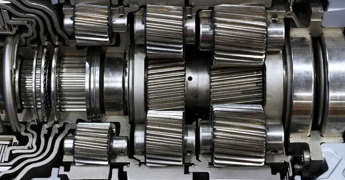
Picture a gearbox as a meticulously arranged set of gears intricately interlaced within a casing. Its primary function is to receive the drive from a driver unit (electric motor, steam engine, internal combustion engine, or even manual drive) and transmit the optimized drive to the driven unit. The driven unit could range from a machine tool (like a lathe or drilling machine), a vehicle (car or truck), a printer, food processing machinery, or any other machinery.
So, why is a gearbox essential? Why can’t we link the driver unit directly to the driven unit?
Driving uphill, cruising through a flat road, or navigating roads in between each demands varying torque levels. Furthermore, the speed dynamically changes: slower while ascending and faster on even surfaces.
If the engine were directly connected to a vehicle’s wheel (via a two-gear set or sprockets and chain), we’d be stuck with a single speed which isn’t practical for varying terrains. By incorporating a gearbox between the engine and the wheel, we introduce a range of different speed options, ideal for uphill climbs, flat road navigation, and traversing at medium or high speeds.
This principle applies similarly to industrial machines. For instance, a lathe machine operator needs different speeds/torque levels for operations like rough turning, finish turning, boring, threading, or polishing. A strategically placed gearbox between the electric motor and spindle shaft offers an array of speed and torque options, enhancing the machine’s utility and efficiency.
Different Types of Gearboxes and Their Practical Uses
Gearboxes, the powerhouse of countless machines, aren’t one-size-fits-all. They morph in tune with their roles, varying from one field to another. In industry, we describe them as industrial gearboxes, while their car-oriented siblings are termed automobile gearboxes.
Let’s explore the types of gearboxes and their interesting uses:
Industrial Gearboxes
- Coaxial or Inline Helical Gearbox: Known for their durability, theses gearboxes are used in heavy load applications.
- Parallel Shaft Helical Gearbox: Recognized for their efficiency, these gearboxes are applied in areas requiring torque transformation.
- Bevel Helical Gearbox or Right-angle Gearbox: As the name suggests, these gearboxes are used for 90-degree transmissions, particularly in heavy-duty industrial machinery.
- Skew Bevel Helical Gearbox: These provide variable direction and speed, making them beneficial in applications such as conveyor systems.
- Worm Reduction Gearboxes: Exceptionally quiet and efficient, you will find these in heavy-duty applications for reducing speed and increasing torque.
- Planetary Gearbox: With the idiosyncratic planetary gears revolving around a central sun gear, they are usually found in space crafts, wind turbines, and other high-precision applications.
Automobile Gearboxes
- Manual Transmission (Constant-mesh Transmission) Gearbox: Quintessential to many vehicles, it allows a smooth driving experience with the perfect blend of speed and torque.
- Pre-selector Transmission Gearbox: Offering smooth gear changes, it finds its place in buses and racing cars where pre-selection of gears is required for constant speed.
- Torque Converter: Typically found in automatic vehicles, it ensures a smooth flow of engine power to the transmission.
- Dual Clutch Transmission (DCT): Housing two clutches for even and odd gears, this gearbox provides a swift, seamless gear-changing experience in high-performance vehicles.
- Continuously Variable Transmission (CVT): Ensuring optimal engine efficiency, this gearbox is increasingly finding its place in modern vehicles for its ability to provide a variety of gear ratios.
A. Industrial Gearboxes | Types of Industrial Gearboxes
Industrial gearboxes are an integral part of industrial machinery and machine tools. They transfer power from the primary driving force to the driven shaft. This machinery enhances the driving force, converting it into high torque or speed and then delivering it to the driven shaft using a predetermined set of gears.
Gearboxes can be either single-speed or multispeed. Multispeed variants are typically seen in lathes, drill machines, milling machines, and CNC lathes. Various sectors utilize industrial gearboxes, including agriculture, cement manufacturing, mining, and machine tools.
Industrial gearboxes employ various types of gears, such as spur gears, designed with straight teeth, and helical gears, featuring teeth set at an angle. Other types also include bevel gears and worm and worm wheels.
A standout feature is the use of helical gears, which are more desired than their spur counterparts. The reason for this preference is two-fold:
- When meshed in a gearbox, Helical gears provide more teeth contact between each other, creating a constant connection. This is unlike spur gears, which have less continuous contact.
- Helical gearboxes are more efficient and consume less power.
Helical gearboxes, made up of helical gears, are typically employed for heavy-duty industrial applications. A few examples include crushers, construction machinery, and extruders.
1. Coaxial or Inline Helical Gearbox (Concentric Gearbox)
Inline helical gearboxes are engineered for heavy-duty applications due to their high-quality construction and ability to handle large loads and gear ratios. This type of gearbox features driver and driven shafts that share the center line (coaxial) but operate independently. Power transmission occurs via gears mounted on a shaft parallel to the coaxial axis.
Typical Uses: Construction machinery, grain handling machines, and other heavy-duty operations.
2. Parallel Shaft Helical Gearbox
The parallel shaft helical gearbox operates with its driver and driven shafts parallel to one another in the same plane, employing helical gears for functioning. This type of gearbox is commonly used in heavy machinery.
Typical Uses: Conveyors, agitator shafts, industrial pumps, heavy-duty mixers, blenders, and more.
3. Bevel Helical Gearbox (Right Angle Gearbox)
A mix of helical and bevel gears characterizes the bevel helical or right-angle gearbox. The helical gears pass power from the driver to a bevel gear pinion, which subsequently drives a bevel gear at a 90° angle. This specific kind of gearbox is responsible for transmitting rotational motion between two non-parallel, cross-sectioned shafts at a 90° angle.
Typical Uses: Agitators for blending and mixing, industrial pumps, quarries, mining, heavy crushers, conveyors, etc.
4. Skew Bevel Helical Gearbox
The skew bevel helical gearbox mirrors the bevel helical model but differs in shaft orientation. Unlike the intersecting 90° angles of the bevel helical gearbox, the skew helical’s shafts are non-parallel and non-intersecting.
This gearbox uses a hypoid pinion and gear to transmit motion at 90°. Despite similarities with bevel gears, hypoid pinion, and gear axes do not intersect with each other: the pinion’s axis is offset from the gear’s axis. Customization of these gearboxes is possible based on user needs.
Typical Uses: Food processing machinery, packaging machines, machine tools, industrial robots.
5. Worm Reduction Gearboxes (Worm Gearboxes)
It comprises a worm gear and a worm wheel positioned at 90° to one another. Worm reduction gearboxes function via the worm driving the wheel. To facilitate this operation, the worm wheel is significantly larger than the worm and possesses more teeth. The worm, resembling a screw, meshes with teeth on the worm wheel’s periphery.
Typical Uses: Industries dealing with fertilizers, chemicals, minerals as well as agitators for blending and mixing, industrial pumps, heavy crushers, etc.
6. Planetary Gearbox (Epicyclic Gearbox)
Driving its name from its resemblance to the solar system, the planetary gearbox comprises a central gear (the sun gear) surrounded by 3 to 4 planet gears nestled within an outer ring gear lined with internal teeth. The sun gear provides the motive force to the planetary gears, which then revolve around the ring gear to transfer motion to an output gear shaft attached to the planetary gears.
Single or double-stage planetary gearboxes exist. In a double-stage planetary gearbox, the gear on the first-stage output gear shaft serves as the sun gear for the second stage’s planetary gear.
Planetary gearboxes are accurate and suitable for precision applications. The machines using planetary gearboxes will have a more extended life period.
Mounting Methods for Gearboxes
For efficient power transmission, gearboxes need to be properly mounted and coupled to the driven shaft. Two primary mounting methods exist:
- Foot-mounted
- Shaft-mounted
1. Foot-mounted Gearbox
A foot-mounted gearbox features two integrated feet on its body with holes to either grout it into the floor or mount it on a sturdy stand. Typically fitted with a flange-mounted motor, this design relies on the motor as the prime mover for driving the gearbox.
Stability is ensured through the use of bolts, nuts, and washers to secure the gearbox firmly to the ground or stand. The driven unit (e.g., an industrial pump or machine) is also mounted on the ground or a stand, with the output shaft of the gearbox and input shaft of the pump or machine connected using a flexible coupling. For this mounting method, it’s essential to securely fasten the foot-mounted gearbox to the ground or stand to minimize vibrations.
2. Shaft-mounted Gearboxes
Shaft-mounted gearboxes and the motor are mounted directly on the machine shaft. The combined weight of the gearbox and motor overhangs on the machine shaft makes this mounting method suitable for simple and lightweight gearboxes.
Key Components of Industrial Gearboxes
- Breather plug: To accommodate changes in air volume due to temperature fluctuations.
- Oil drain plug: To facilitate oil change.
- Oil indicator: To check the oil level.
- Gears: Main components responsible for transmitting motion and power within the gearbox.
B. Automobile Gearboxes
1. Manual Transmission (Constant Mesh Transmission)
Manual transmissions, also called constant mesh transmissions, require the operator to press the clutch, thus disconnecting the engine from the gearbox, selecting the desired gear using a hand-operated lever, and gradually releasing the clutch to drive the vehicle.
This type of gearbox always maintains the gears in mesh, though output gears are not tightly connected to the shaft, enabling free rotation. Through the hand-operated gear shift lever, one can engage one output gear at a time with the needed input gear, transferring the drive to the wheels.
This process depends on the number of available speeds in the gearbox design. Practically, engaging one output gear at a time involves using a synchronizer cone teeth arrangement and a sleeve with internal teeth.
For reverse gear operation, a third gear (idle gear) is introduced to reverse the direction of rotation on the driven shaft.
2. Pre-selector Transmission
Introduced by car manufacturers in the 1930s, pre-selector transmissions offered a simplified operation compared to manual gear shifting. Employing a planetary gear system, this transmission type allows the driver to pre-select gears engaged by pressing a pedal. This action simultaneously disengages the current gear while shifting to the pre-selected gear.
3. Torque Converter
Used in high-end cars, torque converters form part of their automatic gearbox (transmission system). A torque converter operates as a fluid coupling, with oil transferring the drive from the engine to the driven components. Inside a closed box filled with oil is a turbine blade attached to the engine shaft and a driven turbine blade that receives this drive.
As the engine operates, the attached turbine blade rotates, transmitting the drive via the fluid to the driven shaft, which transfers this drive to the wheels. Cars using a torque converter run smoothly and resist stalling.
4. Dual Clutch Transmission (DCT) – also known as Automatic Transmission
DCT is typically used in cars, and it incorporates two clutches (inner and outer), with one managing odd-numbered gears and the other dealing with even-numbered gears. This arrangement facilitates the pre-selection of the next gear, promoting rapid and smooth gear shifting using hydraulic fluid pressure.
Operating this gear system is easy for drivers. Simply pushing the lever to D (drive), R (reverse), or N (neutral) triggers an automatic gear shift. This action sends instructions to the computer managing the dual-clutch and transmission system. By leveraging input from sensors related to the accelerator, engine, and other factors, the computer determines the suitable gear and shifts it through actuators.
5. Continuously Variable Transmission (CVT)
Unlike other transmissions, CVTs do not use gears. Instead, they incorporate two cone-shaped pulleys (driver and driven) connected by a unique belt. Here, the driver pulley is larger than the driven pulley.
During acceleration, the belt is pushed towards the pulley edges, where the larger diameter transmits a higher speed to the driven pulley. This provides infinitely variable speed on a CVT drive. Although this system is common in scooters, some car manufacturers also employ it.
Conclusion
In summary, a solid understanding of various gearbox types is crucial to the automotive and industrial sectors. Each category- manual transmission, pre-selector, torque converter, dual-clutch, or CVT – carries its specific features and applications, offering unique advantages for different operating environments.
Whether you’re choosing a vehicle or industrial machinery, it’s essential to consider the working conditions, personal needs, and performance expectations. Understanding these aspects will guide you to the most suitable transmission system, ensuring enhanced operational efficiency and the longevity and maintained performance of your machinery or vehicle over time.
References


