The turbines are classified into two main types of Impulse-type turbines and Reaction turbines based on how the steam expands through the steam nozzle and impacts the turbine blade. In the impulse turbines, the steam expands at the nozzle and passed over to the moving blades. The moving blades convert the kinetic energy into mechanical energy. In reaction turbines, expansion takes place at the stator as well as at the rotor-blades. The blade passage area varies continuously to allow for a continuous expansion of the steam stream over the turbine blades.
The functions and fields of applications of these two main types of turbines are different. Impulse-type turbines are gas turbines mostly-used on commercial ships, submarine, and navy ships, whereas reaction-type turbines are used on power plants and aircraft turbojet.
Impulse-type Turbines

Steam expansion occurs in the impulse-type turbine at the stationary nozzles; the kinetic energy gets converted into mechanical work on the turbine blade. The whole pressure drop occurs at the nozzles while the pressure remains approximately constant at the blade passages.
As the steam expansion occurs at the nozzles, the steam jet’s expansion action strikes the turbine blades, known as an impulse. The impulsive forces of the steam rotate the rotor. Hence, the impulse-type turbine’s operation depends entirely on the impulsive force of high-velocity steam jets.
The nozzles deliver the steam at high velocity, the high-velocity steam strikes the blades, and work transfer takes place at constant pressure. The steam velocity gradually reduces until it completes its route inside the turbine and gets out with appreciable velocity. The nozzles are fitted at an inclined angle with a fixed angle to the tangent of the rotor wheel. The commonly used nozzles are converging-diverging nozzles due to the large expansion ratio they provide.
The temperature of gases at the rotor level is relatively low, which reduces the risk of creeping: this is an advantage. The velocity of the gases at the outlet of the nozzle guide vanes is high, which causes essential losses due to shocks, friction, and gas stream separation that may cause surging and reduce the turbine’s efficiency.
Impulse turbines are mostly axial flow turbines where they are used for small power applications on which the turbine occupies less space per unit of power.
Compounding Of Impulse Turbines
As the pressure drop occurs at the nozzle of the impulse turbines, the pressure drops from the boiler pressure to condenser or exhaust pressure in one stage. The steam velocity will be too high, which causes the turbine rotor to run at a very high speed. The high rotation speed of the turbine will create various operational issues and disadvantages besides high losses. It is usually necessary to reduce the speed to enhance efficiency.
An improvement to reduce the rotor’s high speed to practical limits in the impulse turbines is necessary to enhance the turbine efficiency. The same is achieved by adding multiple sets of nozzles and blades in series keyed to a common shaft; thus, either pressure of steam or its velocity is absorbed in stages and thus reduces speed.
Compounding is the method of reducing the turbine rotor’s speed by absorbing steam pressure or velocity by adding multiple stages to the turbine.
The three common methods of compounding are as follow:
- Velocity compounding.
- Pressure compounding.
- Pressure-velocity compounding.
Reaction Turbines

Steam enters the rotor under pressure and flows over the blades in the impulse-type turbine. The steam propels the blades and subsequently rotates the rotor by reactive forces of steam jets.
Practically, it is not usual to have a solo reaction turbine; usually, the turbine employs both impulse and reaction principles; the driving force is divided partly impulsive and partly reactive.
The turbine construction consists of a number of rows of moving blades fixed to a shaft with an equal number of fixed blades attached to the casing. The fixed blades are set in a reversed manner compared to moving blades. A set of fixed blades are positioned at the entrance in place of the nozzles, the steam pass through the first row of fixed blades, the pressure drops slightly, and therefore the velocity increases. After then, the steam enters the first row of moving blades, which is an impulse turbine, the direction of the steam changes, which results in momentum; the momentum creates an impulse on blades.
The turbine’s design makes the passage of moving blades creates a small pressure drop in moving blades. Thus, giving rise to increase the velocity and therefore increase the kinetic energy, the kinetic energy rises the reaction in the direction opposite to that of added velocity. Hence, the total driving force is the vector sum of both impulse and reaction forces. The reaction turbine pressure drop occurs in both fixed and moving blades; the blade passages in both are of convergent nozzles shape.
The impulse turbines are partial admission turbines as nozzles do not occupy the complete circumference leading into the blade. On the other hand, the impulse-reaction turbines utilize a set of nozzles on which steam admits to the whole circumference.
The reaction turbine is also known as Parson’s reaction turbine; this type of turbine is very successful in practice and widespread in power plants.
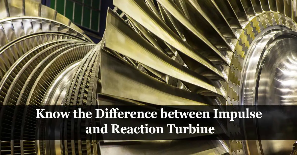
Difference between Impulse and Reaction Turbine
| Comparison | Impulse turbine | Reaction turbine |
| Steam flows | Steam flows in the impulse turbine through nozzles and strikes the moving blades. | Steam flows in the reaction turbine through fixed blades and then flows over moving blades. |
| Pressure drop | Large pressure drop. | Small pressure drop |
| Pressure drop location | Pressure drop takes place at nozzles, and pressure remains constant all over the turbine blades. | Pressure drop takes place in both stator and turbine blades. |
| Blade passage cross-sectional area | The blade passage is of constant cross-sectional area. | The blade passage is of variable cross-sectional area. |
| Blade manufacture | The blade shape is profile type and easy to manufacture. | The blade shape is aerofoil type and difficult to manufacture. |
| Nozzles | Nozzles are located in diaphragms. | Fixed blades are attached to the turbine casing, functioning as nozzles. |
| Rotor construction | Impulse turbine rotor construction is disc or wheel type. | Reaction turbine rotor construction is drum type. |
| Steam admission | Steam admission is partial over the turbine circumference. | Steam admission is full over the whole turbine circumference. |
| Number of stages | The number of stages is less due to the large pressure drop. | A larger number of stages are required due to the small pressure drop. |
| Velocity of steam and turbine blades | The velocity of steam and turbine blades is higher due to the large pressure drop. | The velocity of steam and turbine blades is lower due to the small pressure drop. |
| Power application | Impulse turbines are used for small power applications. | Reaction turbines are used for medium and higher power applications. |
| Size | Impulse turbine occupies less space per unit power. | Reaction turbine occupies more space per unit power. |
| Degree of reaction | The degree of reaction is zero. | The degree of reaction is greater than zero (between 0~1) |
| Energy conversion | The entire energy is converted into kinetic energy.
|
No energy conversion takes place in the reaction turbine.
|
| How it works | The work is done by the change in the kinetic energy of the jet in the impulse turbine. | The work is done partly by the change in velocity but almost entirely by the change in the reaction turbine’s pressure. |
| Newton’s Law | Newton’s second law applies to the impulse turbine. | Newton’s third law applies to the reaction turbine. |

Turbine Classification
Turbines are classified as impulse-type turbines or reaction turbines based on how the steam expands through the nozzle and impact a blade. However, there are several different ways to classify the turbine as follow:
- By the action of steam: Impulse or Reaction.
- By the direction of steam flow: Axial, Radial, Mixed, Tangential, Helical, or Reentry.
- By the inlet steam pressure: High Pressure, Medium pressure, or Low pressure.
- By the final steam pressure: Condensing or Non-condensing.
- By the source of steam: Extraction or Accumulator.
Reference:
- Wikipedia – Turbines.