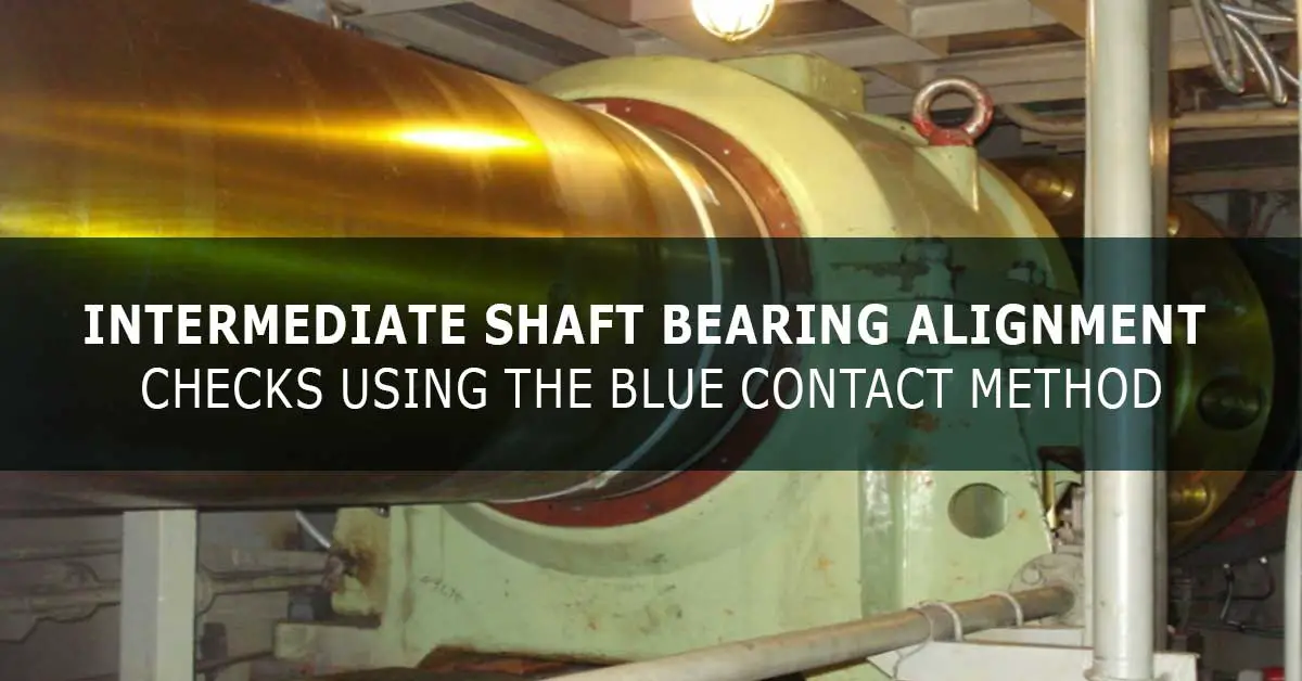
When work has been conducted on a vessel propulsion shaft line, it is sometimes required to check the local alignment between an intermediate bearing and the shaft journal to confirm the shaft journal is evenly supported by the full axial length of the bearing. This is usually achieved by the soft blue contact check method.
Circumstances where an intermediate bearing may require a soft blue contact check
- Where the bearing shell has been replaced. Particularly if the original bearing had suffered heavy wear at one end.
- Where a bearing casing has been removed from its seating, and the chocks had not been individually marked.
- Where a vessel has grounded and suffered hull deformation under the intermediate bearing seating.
It should be noted that a soft blue contact check would not be conducted where the bearing shell is located in a spherical housing within the bearing casing, i.e. so-called ‘self-aligning’ type bearings. With this arrangement, the bearing shell does not have an exact fixed position, either in the rotational or longitudinal angular directions. Note that the bearing shell is rigidly locked once the bearing cap is tightened.
Other situations where soft blue is used for a contact check
- To confirm a full mating surface contact between a propeller hub bore and propeller shaft taper. A blue contact check and polishing/ scraping are typically conducted during the fitting of a new propeller or propeller shaft.
- To confirm a full contact between a valve disc and its seat in a globe valve.
- To confirm a full contact between a valve disc and its seat in an engine cylinder head exhaust valve.
Soft blue is comprised of Prussian blue pigment in a non-drying paste.
Taking bearing’s contact pattern imprint
Ideally, the vessel should be afloat for the contact check as there are differences in the hull shape, hence also the position and angle of the intermediate bearing seating, between when the vessel is supported by dock blocks versus normal water pressure. The bearing body holding-down bolts should be fully tightened.
Preparations:
- The temperature probe is removed (pocket and RTD sensor). This is essential for any task involving the lower bearing shell.
- The bearing cap is unbolted, lifted, and fleeted aside. The chain block, strop, and shackles must all be clean, i.e., do not use any lifting gear that has been in the dock bottom and may have blasting grit residue.
- The bearing should be drained of oil, although this is not absolutely necessary. If the oil is not drained, then great care must be taken that dirt or lose items do not enter the sump.
- A plate is usually bolted on one side of the bearing casing joint so as to prevent the bearing shell from rotating out of the casing when the shaft is rotated.
The exposed upper half of the shaft journal is coated with a soft blue past. A brush or roller can help spread the paste; in any case, this may take 10 minutes or longer. The coating should be thin and even across the axial length of the journal. The coating should be transparent, i.e., features on the journal surface should be clearly visible. Tools are available to measure coating thickness, e.g., wet film wheel, and the thickness should be about 0.005 mm (5μm).
The shaft is rotated one full revolution in the ahead direction using the turning gear. This will transfer some of the blue paste to the bearing surface according to the variations in contact. The clearance between the shaft and the bearing casing labyrinth seal gland using feeler gauges at the bottom, port, and starboard positions for the aft and forward ends should also be checked. This is to ensure the shaft is not contacting the bearing casing.
For a bearing half-shell, i.e., not a tilting-pad type, you should also measure the shaft to bearing clearance using feeler gauges at the port and starboard positions for each end to check if the bearing body is skew to the shaft in the horizontal plane. This is sometimes referred to as clearance at the bearing ‘horns.’ The shaft is then raised about 0.5 mm to 1.0 mm using a hydraulic jack with a dial indicator to measure the lift. The dial indicator should be positioned under the shaft and left in place to allow any drift of the jack to be monitored. The shaft turning gear starter should be locked in the off position while the jack supports the shaft.
The bearing shell should be marked at forward, and aft ends. Multiple bearing shell sections should be numbered, and the installed position noted. The bearing can then be rolled out from its housing. This can be done using a special tool bolted to the bearing shell half joint face or with eyebolts in the aft and forward faces. Eyebolts must be tight. If the eyebolt is longer than the threaded hole, use washers to ensure proper support of the eye bolt head. Two chain pull positions may be needed to ensure the strop does not abrade and mark the shaft. Hands and fingers should be kept away from edges and interfaces.
Interpretation of the bearing contact pattern
Rotating the shaft in the bearing results in soft blue being accumulated around the contact area boundaries. The contact areas are generally clear of soft blue; also areas where clearance is greater than coating thickness, there is no blue transfer, Figure 1. However, more blue can accumulate at the first leading edge and leave little at contact boundaries further around the bearing.
Shaft rotation can also remove blue from contact boundaries. If a relatively thick blue paste coating is applied to the shaft, then blue can remain in the contact areas after the rotation has stopped, Figure 2. A contact pattern can be photographed or recorded by transfer to a piece of paper where the better contrast can also aid interpretation. Making sense of a contact pattern can be difficult.
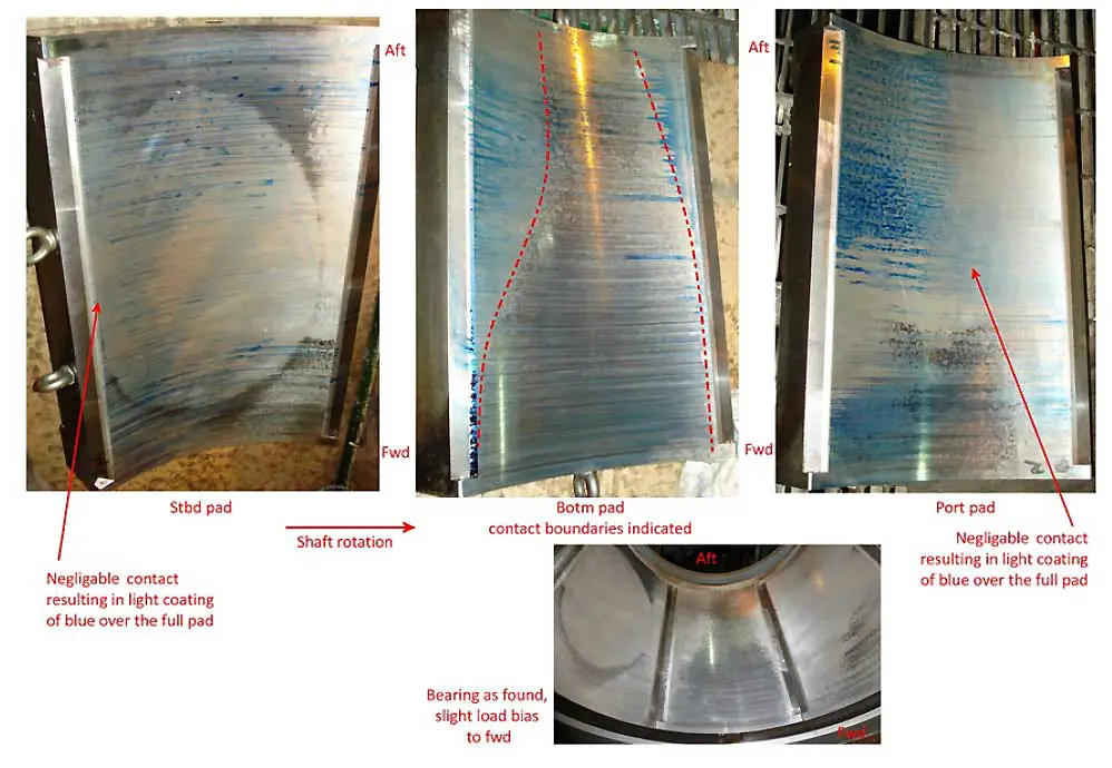
The bottom area of the bearing between 4 o’clock and 8 o’clock is generally considered as the main working area, and inspections should be concentrated accordingly. Criteria for assessing a satisfactory versus unsatisfactory contact pattern may not be available. However, a bearing with zero contact at either end bottom 6 o’clock position would typically be assessed as unsatisfactory. Other alignment errors include horizontal skew between the bearing and shaft (and should correlate with the feeler gauge measurements) as well as hour-glass or barrel-shaped contact patterns.
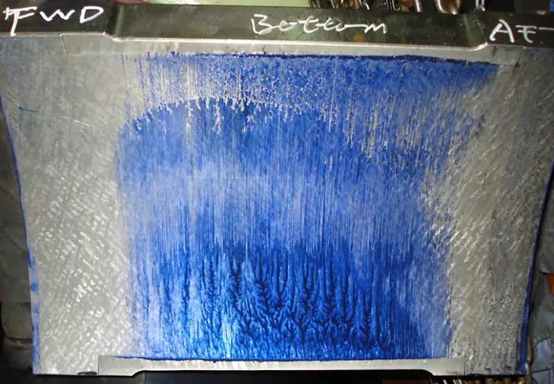
An adverse contact pattern is generally corrected by means of adjustments to the chocks/ shims under the bearing body feet. An adjustment should be equally divided between the aft and forward ends, i.e., up at one end and down the other end, so that the shaft alignment (bearing load) is not altered. (This would be important in the case of a vessel not fitted with a stern tube forward bearing, and the aft intermediate bearing is being checked.) In practice, adjustments tend to be based on trial and error.
An unsatisfactory contact pattern of hour-glass or barrel shape, i.e., having area(s) of zero contact at the bottom 6 o’clock position, can generally only be corrected by scraping. However, before deciding to remove material, the bearing surface should be checked with a straight edge and a flashlight. If measurements of the shaft journal diameter are available, these should also be checked. Hand scraping is recommended as machining tends to remove a greater amount of metal, which may affect clearance, bearing running temperature, and life.
Intermediate Bearing Reassembly
During reassembly, you should check the following:
- Apply oil to the shaft journal and bearing. After the bearing shell is fitted, ensure the hydraulic jack is removed.
- Clean and check the bottom of the sump is clear of any debris.
- For bearings with a self-contained lubrication system, check the clearance between the oil pick-up ring and the scraper is within the manufacturer’s tolerance. Where the oil scraper is affixed by a single screw, a small amount of thread lock adhesive should be used on the threads.
Read also: Jack-Up Test Procedure For Ship’s Propulsion Bearings.

