
Bearing reaction is one of the main parameters to verify the reliability of propulsion shaft alignment; it is defined as the bearing support of propulsion shafting observed at a static condition. We will focus on bearing reactions and methods to measure it, specifically by jack-up test.
It is mandatory to measure that the following main parameters and ensure they are within the acceptable shafting alignment limits:
- Bearing reactions
- Misalignment angles
- Bearing vertical offset
- Gear misalignment (indirect confirmation)
- Crankshaft’s web deflections (indirect confirmation)
Measuring bearing load is usually carried out for engine main bearings, intermediate shaft bearing(s) and forward stern tube bearing. The result is interpreted in connection with the other parameters mentioned above to diagnose any alignment issues. However, in routine checking of the bearing loads, it is usually compared with the designed bearing load, the initial load recorded during vessel commissioning, and bearing maximum designed load specified by its maker.
Bearing Reaction Measurements
Bearing reaction measurement could be conducted either directly or indirectly, and measured by one of the following methods:
- Sag and Gap
- Jack-up
- Strain gauge method
Jack-up measurement is a direct reaction measurement, while strain gauge and sag and gap procedure are indirect methods to measure the deflections and strain in the shaft and correlate those measurements to the bearing reactions.
Bearing Reaction Measurements by Jack-up Method
The jack-up test method is direct reaction measurement procedure on which the reaction of a bearing is measured in correlation with the jack load that is set as close to the bearing as possible.
The bearing reaction is estimated from the relationship between the jack load and the jack displacement.
Required Tools
- Hydraulic Jack: Jack to be selected with known pressure area which will be used in the final load measurement equation, the jack pressure area is found by disassembling the jack and measuring the effective jack pressure area. The jack should not be large, as the accuracy of the pressure gauge is better in the higher pressure range.
- Hydraulic Pump: Any pump with an accurate pressure gauge (Bar), good quality needle valve and pressure adjustment device.
- Dial Gauge: Ordinary dial gauges with 0.01 mm resolution and adjustable mounting on magnetic foot.
- Load Cell: Non-essential tool, however, it improves measurement accuracy significantly.
Jack-up Test Preparation
Record vessel drafts forward and aft, the comparison of the final readings will consider drafts as it affects values.
For Main Engine and Intermediate shaft;
- Measure bearing top and bottom clearance, especially for the two AFT most bearings. If bottom clearance is present, jack-up test for this specific bearing will be useless and further action to take place to restore and bearing load as per design load distribution.
- Measure the thrust bearing temperature, intermediate shaft bearing foundation and bottom tank(s) under the engine and intermediate shaft bearing temperature.
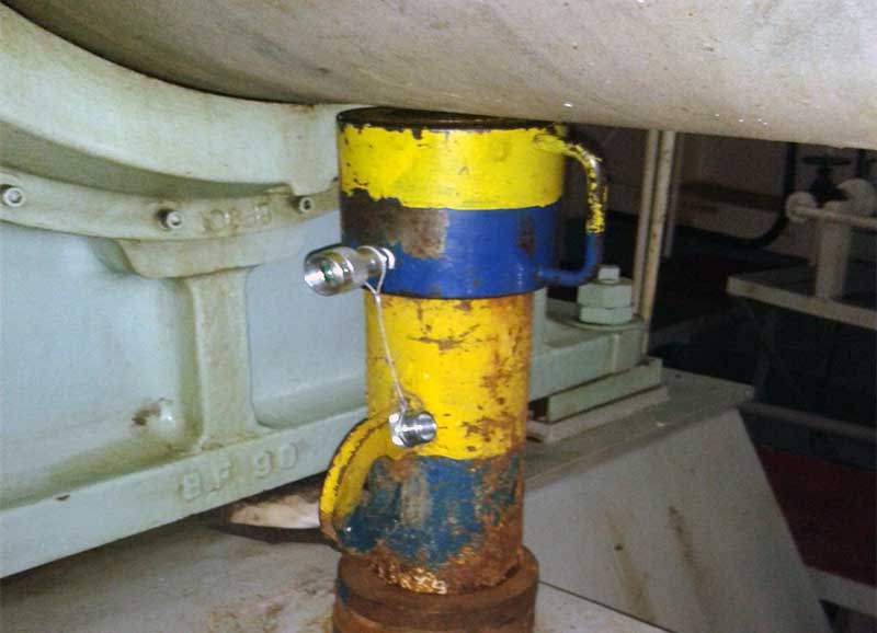
- Hydraulic jack used in the testing has to be located on a stiff foundation and as close as possible to the bearing (usually, jack-up test hydraulic jack foundation is fitted during vessel new building and correction factor is calculated based on this specific location).
- Dial gauge used in the testing should be anchored on a place that is not affected by the lifting and stiff enough that does not move during lifting resulting wrong and inaccurate readings.
For Main Engine only;
- Record AFT most crank web deflection.
- Declutch turning gear from the flywheel, especially when measuring AFT most bearing reaction. If turning gear is engaged, it introduces significant horizontal force resulting in incorrect measurements.
Related article: Sterntube Bearing And Propeller Tailshaft Inspections
Measuring AFT Most Engine Main Bearing
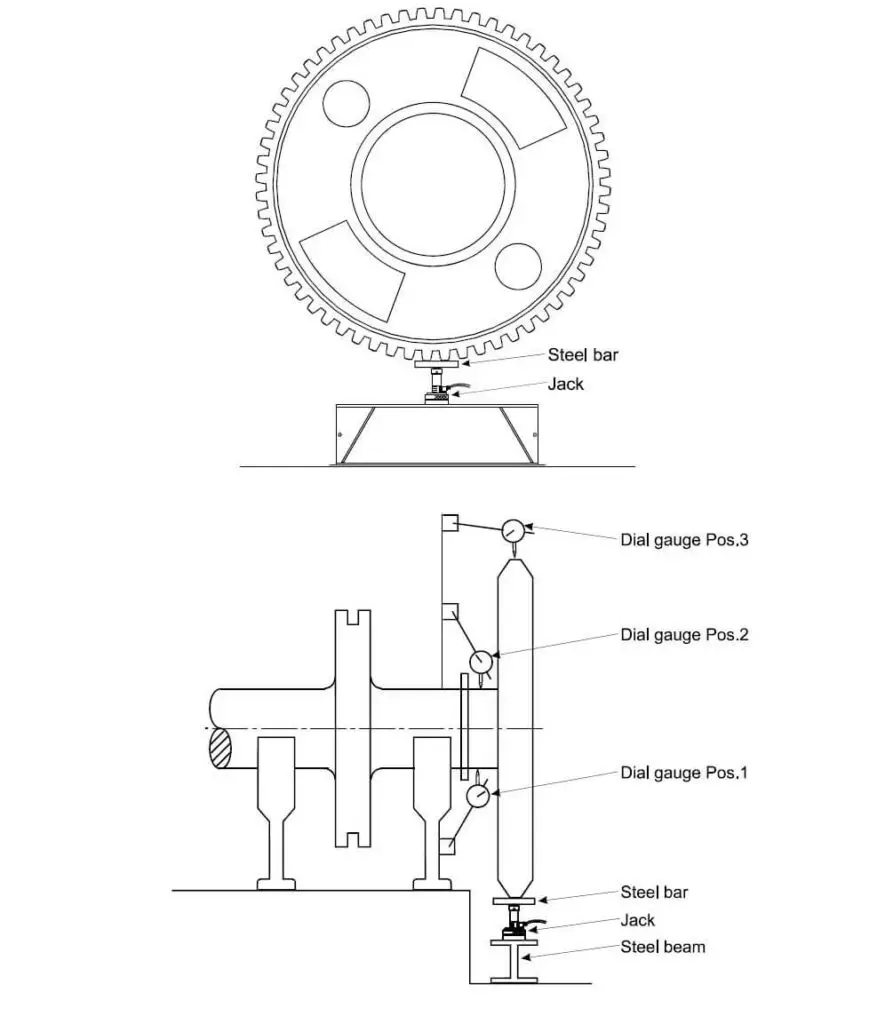
Place the jack below the turning wheel on a stiff foundation, the jack should be placed on two flywheel teeth and solid steel bar to be placed in between for proper load distribution. Proper alignment of the jack while placing it is essential, improper jack alignment creates more friction in the jack resulting in more hysteresis in measurement curves.
Place dial gauge on one of the shown positions above and measure the vertical displacement (movement) of the journal or the turning wheel. Placing the dial gauge between the jack support and the turning wheel will produce incorrect readings; hence, the same should be considered and avoided.
Measuring Main Bearing(s) Except AFT Most
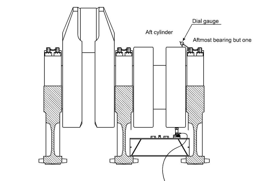
The crankshaft should be turned to keep the crank web in a horizontal position towards the exhaust side. Place the jack-up beam (available with main engine maintenance toolset) and place one jack adjacent to the bearing where the measurement will be recorded. It is preferred to use the provided jack with the engine maintenance toolset (if available). However, any multi-purpose jack may be used with known effective pressure area as previously mentioned.
Place the dial gauge on the main bearing cap and measure the vertical displacement (movement). Placing the dial gauge between the jack-up beam and crank web wheel will produce incorrect readings; hence, the same should be considered and avoided.
Measuring Intermediate Shaft Bearing(s)
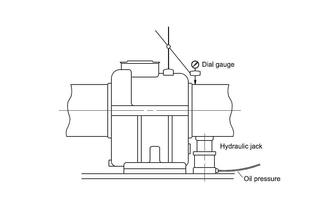
Usually smaller hydraulic jack is used to measure intermediate shaft bearing reaction as bearing load is lower than the main engine main bearing loads. The jack-test hydraulic jack foundation is fitted during vessel new building, and the correction factor is calculated based on this specific location.
Jack-up Test Measuring Procedure
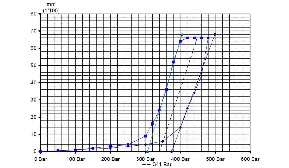
The measurement is recorded by rising the jack pressure and record vertical movement on the dial gauge; reading is recorded with 10 – 50 bar intervals of pressure recorded on the pressure gauge or 0.020 – 0.05 mm displacement recorded on the dial gauge. A smoother curve may be produced when using a specific interval (pressure or displacement) measuring procedure, which will generate more accurate recalculation.
Jack-up until the bearing top clearance is close to zero, which has been previously measured during the preparation phase. If pressure gauge pressure suddenly increases, it indicates that the clearance is zero and the journal is touching the upper bearing shell.
Record as many measurement points as practically possible, at list 15 steps on each measuring phase (upwards and downwards).
Internal friction in the hydraulic jack is unavoidable due to (hysteresis phenomenon); hence, it will be noticed that the recorded hydraulic pressure will be higher during lifting than during lowering down. Tangents will be drawn on the upward and downward curves and the correction tangent (frictionless) will be drawn on centre between both tangents and will be the reference for bearing load measurement.
Pressure has to be increased or decreased steadily during upwards and downwards jacking procedure to produce accurate readings and encounter the effect of hysteresis phenomenon.
Data analysis for unloaded or lightly loaded bearing will be challenging; hence, it is recommended to place one dial gauge on the measured bearing journal and one on each adjacent bearings journal (whenever applicable). As well, measurement readings to be recorded on smaller intervals 10 bar on pressure gauge or 0.020 mm on dial gauge whatever is the followed recording method.
Jack-up Test Measurements Analysis and Load Calculation
The measured points to be plotted and connected, generating several straight lines with different slopes, the point between each slop will be defined as “breakpoint”. Each breakpoint is practically indicating that the supporting points in the shafting decreases due to one of the adjacent bearing(s) load becomes zero when lifting the shaft to this vertical displacement.
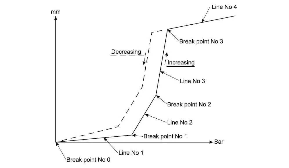
Breakpoint:
- No 0: Starting point when there is no load on the hydraulic jack.
- No 1: The load is completely shifted to the jack and fully released from the bearing.
- No 2: The load is shifted to the jack from the second bearing and fully released from the second bearing.
- No 3: The pressure at this point will suddenly increase rapidly, and it indicates that the clearance is zero, and the journal is touching the upper bearing shell.
Line:
- No 1: This Line indicates the transmission of the load from the bearing to the hydraulic jack.
- No 2: This Line indicates the transmission of the load from the second bearing to the hydraulic jack.
- No 3: This Line indicates the transmission of the load from the third bearing to the hydraulic jack.
- No 4: The pressure will increase rapidly, and the journal does not elevate much because this indicates that the clearance is zero, and the journal is touching the upper bearing shell.
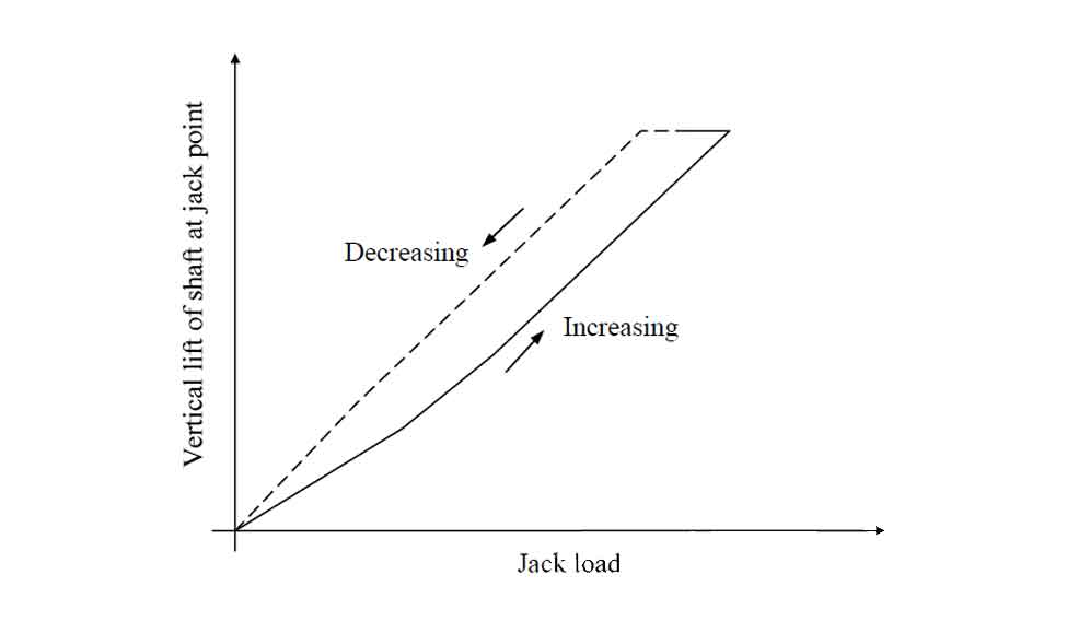
If no breakpoint appears and the jack-up curve plotted as above, this indicates that the bearing is almost not carrying any load and the reaction value is nearly zero.
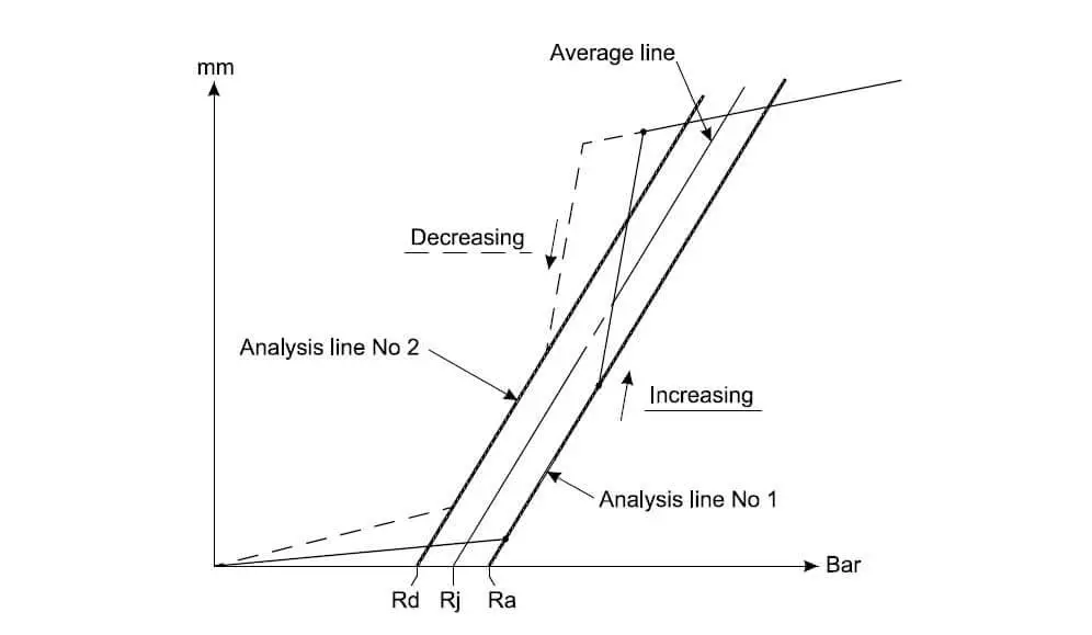
The jack load reaction is presented by (Rj), to calculate the reaction (Rj) two tangent (A & B) will be drawn on plotted points curve which given the name “Line No 2” on the above explanation graph.
Tangent A: Is a line drawn parallel to Line No. of the upward curve (Pressure increase points).
Tangent B: Is a line drawn parallel to Line No. of the downward curve (Pressure decrease points).
(Ra) is the reaction of the drawn tangent “A” at a lift of 0 mm
(Rd) is the reaction of the drawn tangent “B” at a lift of 0 mm
Ra = P (a) x A x 1/982 (tons*)
Rd = P (d) x A x 1/982 (tons*)
* (1/982 is to convert from KN to ton, 1 ton ≈ 9820 Newton)
The load reaction then calculated, Rj = 0.5 (Ra + Rd)
Measurement units
Bearing reaction R, measured in Ton (T)
Jack piston diameter (D, d), measured in Centimetres (cm)
Jack pressure area (A), measured in Square centimetres (cm2)
Pressure (P), measured in Bar
Correction factor (C), No unit
Hollow jack pressure area: A = (D2 – d2) x π/4, where D, is the outer diameter and d, is the inner diameter.
Solid jack pressure area: A = D2 x π/4
Since the jack is not positioned at the centre of the bearing, the calculated load reaction (Rj) is not precisely the bearing reaction (R), the difference is corrected by multiplying the calculated reaction (Rj) into correction factor (C).
Hence, the bearing reaction, R = C x Rj.
Correction Factor (C)
As an output from shaft alignment calculation, the actual correction factor (C) will be calculated and provided in shafting alignment booklet.
However, in the event of non-availability of shafting alignment calculation booklet, the following correction factor values can be used as a rough guideline:
AFT most engine bearing, jack-up under the turning wheel: C = 1.30
Remaining engine bearings: C = 0.90
Intermediate shaft bearing(s): C = 0.98
Final Thoughts and Points to Consider
The bearing reactions are initially calculated in the straight shafting line condition, for small ships, even a straight shafting alignment, in most cases, meet the relevant requirement. Still, for large ships, the results from the straight shafting line condition usually do not meet the required acceptance criteria due to the deflection of the shaft caused by weight distribution.
The AFT stern tube bearing is overloaded, while the FWD Stern tube bearing tube is loaded in the opposite direction. Hence, the alignment must be corrected by appropriate measures of bearing offsets which are determined, resulting in acceptable target bearing reactions.
For shaft alignment verification, FWD stern tube bearing and intermediate bearing(s) jack-up test is conducted to evaluate if they are producing satisfactory reactions. Further evaluation can be done by preforming Jack-up test for the main engine bearings, especially the two AFT most bearings.
If it is not possible to conduct the test for any operational reasons, strain gauge method to be undertaken, or at least crankshaft deflection to verify that they comply with manufacturer acceptance criteria.
For runout verification, a jack-up test may be used; however, it is not the best method for such verification as measurements are done of certain rotation steps at the time (usually 0, 90, 180, 270 degrees).
Jack-up test accuracy depends on various factors contributing to obtaining the results (e.g. vessel drafts, tools condition, and experience of the technician performing the test). Generally, more accurate results may be obtained from higher loaded bearings. On average, an accuracy of ±15% can be expected from the high loaded bearing.
References:
- American Bureau of Shipping: Propulsion Shafting Alignment.
- MAN B&W Diesel A/S: Production Recommendation, Bearing Load Measurement by Jacking Up.
- Class NK: Guideline on Shafting Alignment.