It is usual to periodically measure crank web deflections in an engine to monitor main bearing wear or changes in shaft alignment. Main engine deflections are typically also measured before and after work on propulsion shafting, shaft line bearings, or main engine bearings to assure no significant change in engine alignment condition.
The measurement principle is that curvature of the crankshaft, due to height/ offset differences between main bearings, will cause adjacent crank webs to deviate from parallel. The angular misalignment can be found if a distance measuring gauge is fitted between the crank webs off-center opposite the crankpin, and the crankshaft is rotated through a full revolution.

Deflection indicator instrument
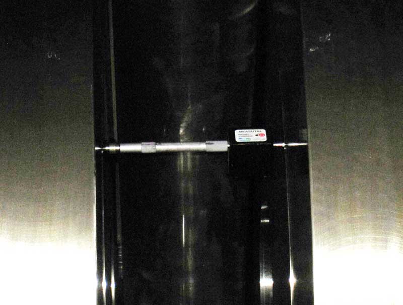
Engine manufacturers generally supply a crank web deflection indicator with a new construction vessel. Indicators are available with a dial indicator or a strain gauge-based displacement sensor.
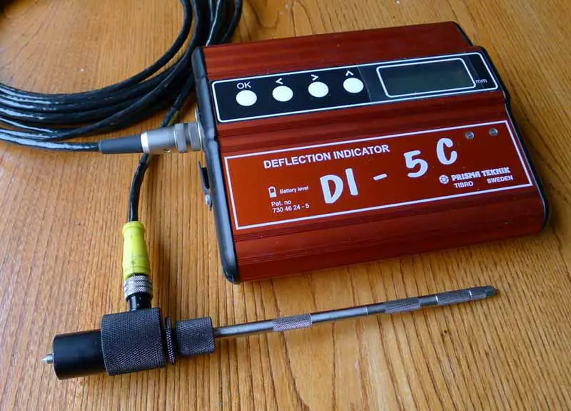
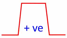
It is important to note that all dedicated crank web deflection instruments indicate a positive value for an opening/ increasing gap. This is the opposite of a normal workshop dial indicator indicating a positive value for an inward spindle movement/ closing gap. Any report of deflection measurements should state positive values indicate an opening gap or have the symbol as shown.
Engine Crank Web Deflection Measurement
Working inside a two-stroke main propulsion engine can be dangerous. Care, not speed, should be your main thought when moving around inside a large engine. Overshoes should also be worn inside the engine to avoid dirt or grit being carried into the engine on the soles of boots. It is usual not to run the engine lube oil pump during crank web deflection measurements. However, this is at the discretion of the vessel Chief Engineer.
The vessel and engine conditions should firstly be recorded:
- Engine temperature by jacket cooling water and thrust bearing (if applicable).
- Vessel draughts aft and forward for measurements on the main engine.
- Propulsion engine deflection measurements are generally only conducted with the vessel afloat.
- If steam heating has been on lube oil or other adjacent machinery/ tanks within the previous 8 hours.
- The time when measurement commenced.
For a two-stroke main propulsion engine, rotate the crankshaft so that the measurement cylinder crankpin is on the fuel pump side near the bottom dead center. The distance gauge can then be mounted between the crank web faces at the exhaust side of the connecting rod. After fitting the distance gauge, rotate the crankshaft until the gauge is about 30 mm from the connecting rod.
For a four-stroke engine, doors on both sides of the crankcase generally need to be opened for access to fit and read the deflection gauge. If doors on only one side of the crankcase are opened, then the deflection gauge would need to be fitted from the open side, and a mirror used to read the dial indicator type gauge. Crankshaft rotation for the measurement would then start from the open side of the crankcase.
Mount the distance gauge by fitting the spindle end pointed tips in the small conical recesses on the crank web faces. Take care not to drag the spindle tips on the crank web face. Gently rotate the distance gauge back-and-forth a few times to ensure the spindle tips are correctly seated in their recesses.
The mounting points are 180° to the crankpin and away from the main journal centerline. On a four-stroke engine, one-piece crankshaft, there may be two mounting points in each crank web face, one approximately in-line with the main journal outside diameter for checking during manufacture. You would likely fit the distance gauge in a second mounting point that may be located at a greater radius from the crankpin, perhaps on the counterweight, so the instrument is not fouled by the connecting rod large end. On a slow-speed, two-stroke engine, built-up crankshaft, there may also be two conical recesses in each crank web face. The distance gauge is fitted in the smaller recess, usually about 2 mm diameter and 20 mm inside the main journal to crank web interface diameter. The larger diameter recess at the main journal to crank web interface indicates if relative rotation has occurred between the crank web and main journal.
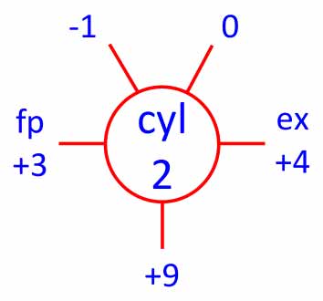
Once fitted, the distance gauge length should be adjusted, so the indicator is near mid-range. The indicator should then be set to zero. The crankshaft can then be rotated clockwise, as viewed from the drive end, and stopped to record the indicated deflections with the distance gauge at; horizontal exhaust side, vertical bottom, horizontal fuel pump side, and vertical top fuel pump side positions. Take care at the top fuel pump side to stop when the gauge is about 30 mm from the connecting rod. The results can be recorded in a diagram for each cylinder as shown with values located per the gauge position. Values are usually in 1/100 mm units. It is important to correctly record the sign of each value as a wrong sign would result in the maximum possible error.
For the aft-most cylinder, measurements should be made in the clockwise and counter-clockwise directions and recorded in separate diagrams. Reverse the crankshaft rotation after the vertical top fuel pump side measurement and repeat through to the exhaust side position. The reason is the possible lifting of the No 2 from the aft main journal in its bearing due to forces from the turning gear to rotate the crankshaft. This can cause inaccurate vertical direction deflection values. If different values are found for the two directions, there are two possible results:
- For turning gear located on the fuel pump side of the engine, the clockwise direction measurements for the vertical and horizontal positions should be used.
- For turning gear located on the exhaust side of the engine, the counter-clockwise direction measurements for the vertical positions should be used. The clockwise direction measurements should be used for consistent conditions for all main journals and cylinders for the horizontal positions.
The top fuel pump side value should ideally be less than about ±0.02 mm. In the event of a greater value, the discrepancy cause should be found by repeat measurements. However, in practice identifying the cause and eliminating the difference can be difficult.
On a two-stroke main propulsion engine, the sequence of cylinders should follow the firing order, e.g., a six-cylinder engine 1-5-3-6-2-4. This gives the minimum rotation between each consecutive cylinder and hence the shortest overall measurement time.
There are typically pairs/sets of crankpins on a four-stroke engine that are in-line; e.g., a six-cylinder engine has three pairs of crankpins in-line 120° apart; 1 and 6, 2 and 5 as well as 3 and 4. For minimum total rotation and reduced time for the measurements, the sequence of cylinders should follow each set of crankpins that are in line. Thus on a six or V12 cylinder engine, one possible order of crankpin measurement would be 1-6-3-4-2-5.
Calculation and assessment of crank web deflections
Crank web deflections may be calculated as follows:
- The vertical plane, bottom position value minus average of the two top position values. A positive difference between the bottom and top would indicate the section of the crankshaft was sagging.
- The horizontal plane, fuel pump side minus the exhaust side values. A positive difference would indicate the section of the crankshaft was sagging towards the fuel pump side.
An example calculation is shown below. Some engine manufacturers also provide limits for differences in deflections between adjacent cylinders; this is shown in the example.
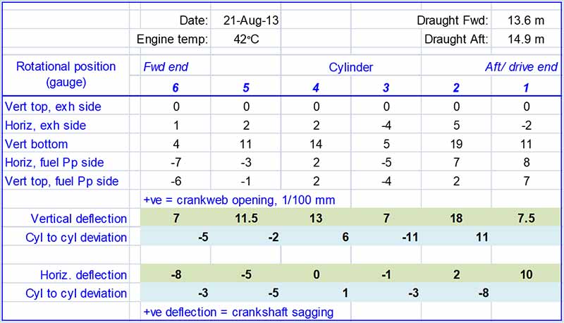
Note that if the difference calculation is reversed, e.g., as top minus bottom, then the sense of crankshaft curvature is also reversed, i.e., a positive deflection would indicate hogging. Rotational position may be noted by the gauge or crank pin. This should not be confusing if you recall that there will be two values for the gauge at the top and one value for the gauge at the bottom. Rotational direction can also be identified from the start position, where the value will be zero.
Crank web deflection results are generally compared to recent previous results and assessed against the engine manufacturer’s allowable limits. Comparisons should be made for similar vessel draught aft and engine temperature. If there are significant differences, the vessel records should be reviewed for variations in deflections against draughts and engine temperature changes.
Note the following regarding engine manufacturer specified limits for crank web deflections:
- The allowable limits for a vessel in service and typically different from the limits for a vessel under construction (generally more stringent). Ensure that the correct limits are applied.
- The limits for the aft-most/ drive end cylinder may differ from the limits for other cylinders, i.e., cyl 2 to cyl (N-1). This provides an allowance for bending moments from the connected shafting or machinery.
- The forward-most/ non-drive end cylinder limits may differ from the limits for other cylinders to allow for the difference in bending moment from the torsional vibration damper.
Related Articles:
- Jack-Up Test Procedure For Ship’s Propulsion Bearings.
- Intermediate Bearing Alignment Checks Using The Blue Contact Method.

