The concept of a movable device to steer a ship has been in use since ancient Egyptians built the ships in the 4th millennium BC. It started from using side-mounted steering oar continually developing to the current advanced various steering systems.
The modern ship has to have a means for steering with adequate strength and suitable design; the steering device should demonstrate the capability of steering the ship at maximum ahead service speed. Steering is achieved using rudders, foils, flaps, steerable propellers, side thrusters, jets, or a combination of these devices. The selection of a suitable steering system is usually based on the ship’s geometry, type, and application.
The following article will introduce you to ships rudders and steering components, drydocking surveys, and how to deal with any associated repairs.
Types of Ship Rudder
Rudders are typically categorized based on their Balance Ratio; the balance ratio is the ratio of the blade area situated forward of the rudder turning axis or rudder stock to the total rudder blade area.
Balanced rudder
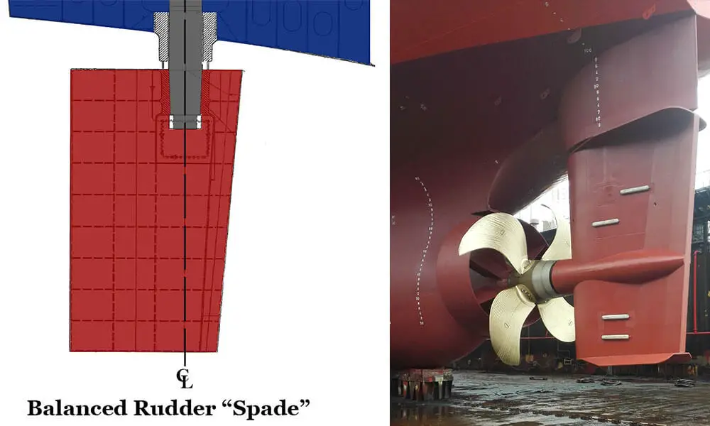
A rudder with a part of the blade area (typically 20%~40% of its area) puts forward the turning axis. The area forward of the turning axis will cause water pressure on this portion to counterbalances the water pressure of the after portion. The resultant moment on the stock will be zero; thus, the steering gear can be lighter and smaller.
The subcategories of balanced rudders are as follow:
1. Spade rudder
A rudder that provides maximum rudder force at high rudder angles. The drawback of spade rudders is the thick rudder profile that results in large diameter rudder stock to carry the rudder forces.
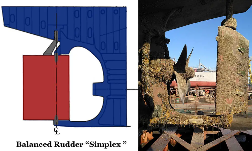
2. Simplex rudder
Like spade rudder, it consists of a rudder blade connected to rudder stock; however, the rudder blade is supported from the lower end by a lower pintle.
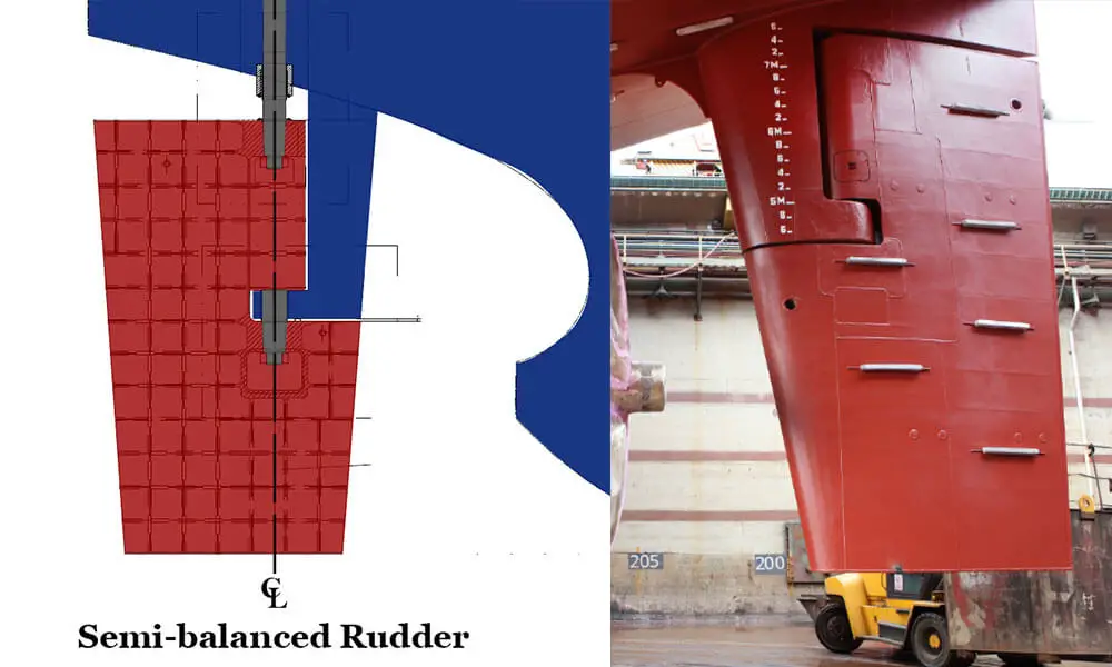
Semi-balanced rudder
A rudder with a certain part of the blade area put forward of the turning axis. Like the balanced rudder, the certain area forward of the turning axis will cause water pressure on this portion to counterbalances the water pressure of the after portion.
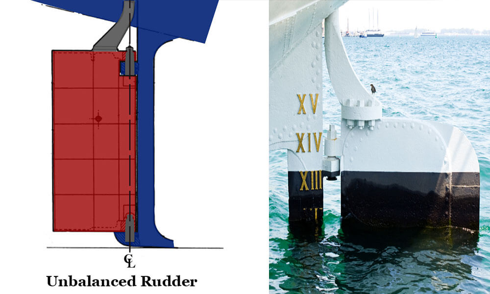
Unbalanced rudder
A rudder has its entire area after the rudder turning axis.
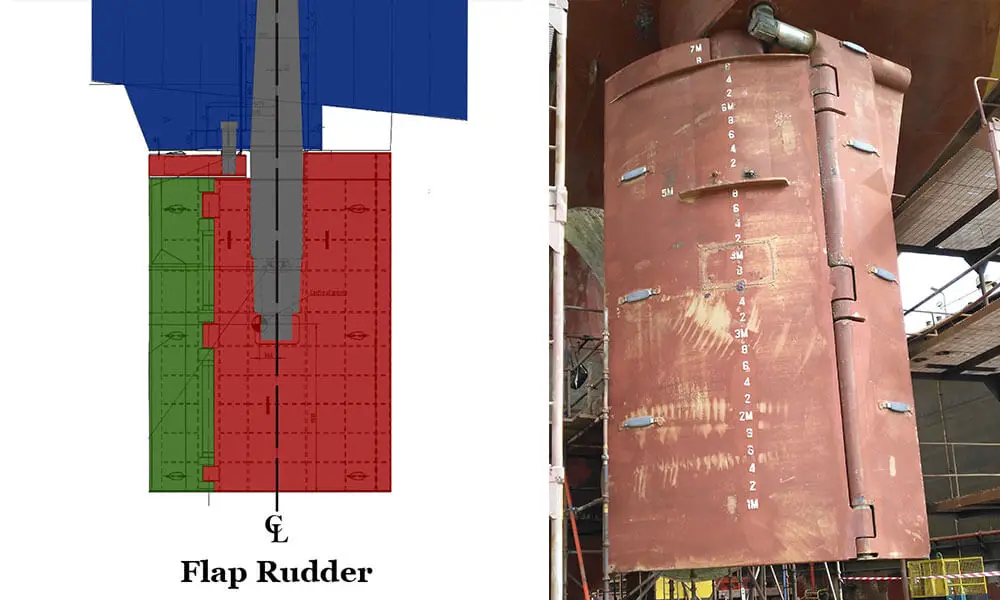
Flap rudder
A rudder consists of a blade with a mechanically or hydraulically activated trailing edge flap. The trailing edge flap produces a variable angle as a function of the rudder angle. Flap rudders deliver high-lift per rudder angle and better maneuverability than conventional rudders of similar shape, size, and area. The most popular flap rudder is the Becker rudder.
Steering System and Associated Rudder Components
The steering system is a system that steers the ship when the ship is underway. The conventional steering system consists of steering gear, a steering control system, a rudder stock, a rudder blade, and associated components. The steering gear provides a rudder blade movement through rudder stock in response to a signal of ordered rudder angle from the bridge.
A. Steering gear
The steering gear is the machinery that applies torque to the rudder stock necessary for effecting movements of the rudder. Two main categories of the steering gear are the main steering gear and auxiliary steering gear.
- Main steering gear – the type of steering gear necessary to steer the ship under normal service conditions.
- Auxiliary steering gear – the type of steering gear essential to steer the ship in the event of failure or malfunction of the main steering gear. The auxiliary steering consists of separate components other than any component of the main steering gear.
The steering gear system is either electric, electrohydraulic, or hydraulic. The electric system consists of an electric motor and its associated electrical equipment; the electrohydraulic system consists of an electric motor and its associated electrical equipment and is connected to a hydraulic pump that provides the hydraulic pressure to run the system. The hydraulic steering gear system consists of a hydraulic pump driven by a separate engine or any other driving unit.
Two common types of electro hydraulically-powered steering gears are the ram-type and the rotary vane.
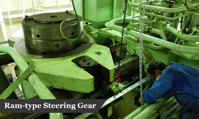
1. Ram-Type Steering Gear
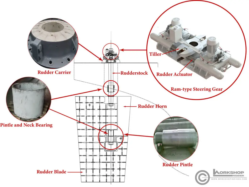
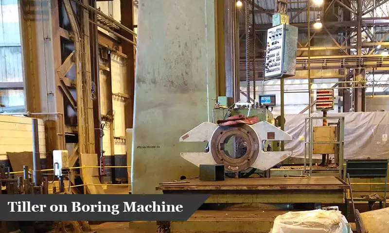
A ram-type steering gear consists of hydraulic rams (hydraulic actuator or rudder actuator), typically two or four, depending on the design. The hydraulic rams are connected to the tiller. Tiller is an arm attached to the rudderstock which turns the rudder. The hydraulic actuator is either connected directly to the tiller through connecting pins or through a slide mechanism that consists of a block pivoted to the tiller arm and guided by a vertical crosshead pin. The block is arranged to slide on the tiller arm so that the moment arm increases as the rudder angle increases. This slider mechanism imparts maximum torque at 35° of rudder movement.
The hydraulic rams convert hydraulic pressure into mechanical action to move the rudder by one or two hydraulic pumps. Typically, the system operates with two independent pumps. Each pump can operate separately and work as a backup system in case of failure of any pump. Therefore, with the two independent pumps system, ships can waive the classification society requirement of having auxiliary steering gear.
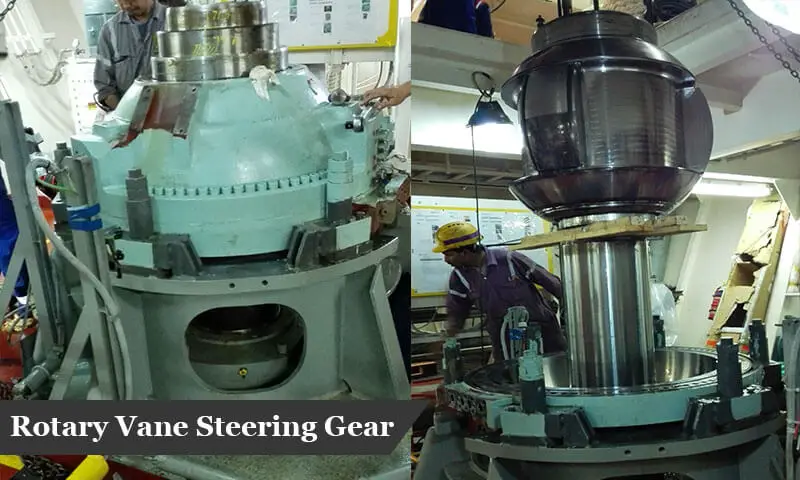
2. Rotary Vane Steering Gear
A rotary vane steering gear consists of a rotor with vanes attached to the rudder stock and stator fixed on a foundation in the steering gear room. Typically, there are two or three vanes on the rotor and an equal number on the stator that form pressure chambers. The system works by introducing pressure into the chambers formed between the stator and the rotor. The pressure increases in the appropriate compartments proportionally to the required torque for effecting movements of the rudder. The pressure reacts against the fixed vanes moving the rotor to the desired rotational direction and subsequently moving the rudder.
A rotary vane steering gear allows a rudder movement degree up to 65°, which is a great advantage of this steering system.
Difference between Ram-Type Steering Gear and Rotary Vane Steering Gear
From the above two systems explanation, it is evident that the two steering gear systems are entirely different from the design and operational point of view; thus, each type has its advantage and drawback.
The rotary vane steering gear is generally smaller than ram-type steering gear of equivalent capacity. The working hydraulic pressure is lower for the rotary vane type as the effective working area is larger than the rams’ total area in the ram-type steering gear.
The maximum degree of rudder movement is another difference between the two steering types. Rotary vane steering gear allows a degree of rudder movement that may reach up to 65° in some models; in contrast, the ram-type steering gear is limited by the stroke of the cylinders and the path of the slider mechanism achieving a maximum degree of rudder movement of 37° or below.
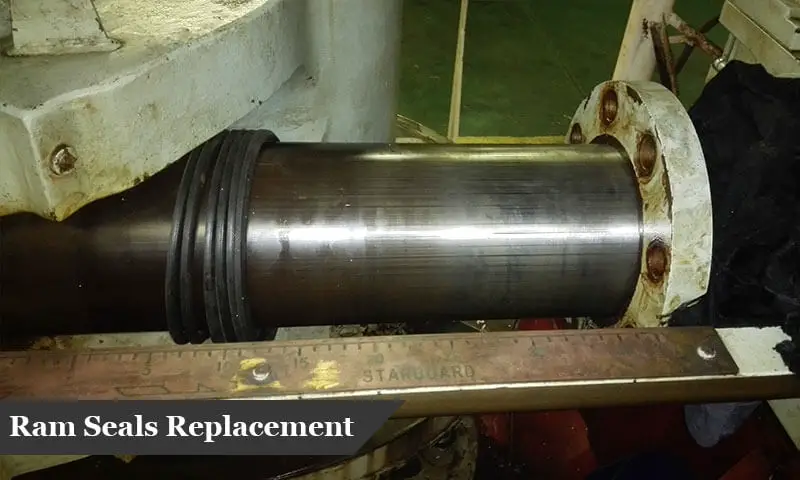
Reliability and possible of rectifying faults when they arise make a difference between the two types. Whenever any fault occurs inside the rotary vane unit, the ship may lose steering completely. In contrast, ram-type steering gear consists of four hydraulic actuators, so if one ram fails, it can be isolated for repair; thus, the steering will not be totally disabled. Repair of rotary vane usually requires a specialized team. However, ram-type working parts are more accessible, rams and ram seals are relatively simple to replace in the event of a necessary repair.
B. Rudder stock
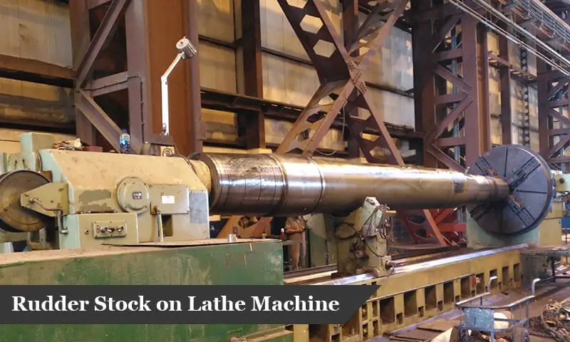
Rudder stock is the shaft that connects the steering gear with the rudder blade; the rudder stock transmits the steering gear’s turning force to the rudder blade to steer the ship. Typically, the rudder stock is made of forged steel. The rudder stock connects to the rudder blade by hydraulic cone fit or flange coupling; and connects to the tiller is by hydraulic cone fit, a key connection, or by clamping rings for smaller rudders. Stainless steel sleeves are fitted in the way of bearings to protect the stock from getting damaged.
C. Rudder Blade
Rudder blade is the main component in the steering system; the rudder blade consists of side plates stiffened by internal vertical and horizontal stiffeners and solid sections made up of cast steel in a conical shape where the rudder stock and the pintle hydraulically fit.
D. Associated Rudder Components
1. Rudder Carrier
Rudder carrier is the component that carries the weight of the rudder, rudder stock, and tiller; it is placed on the steering gear deck below the steering gear or integrated within the steering gear as of rotary vane and some ram-type steering gears.
2. Rudder Pintles
Rudder pintle is a pin that fastens the rudder to the rudder horn, skeg, or sternpost. The pintle consists of a straight part and a conical (Tapered) part. The straight part comes in contact with the bearing for fastening the rudder, while the pintle conical part is used as a coupling to secure the pintle in position.
3. Rudder Horn
Rudder horn is a casting construction that minimizes the bending moment affecting the rudder stock and supports the rudder blade.
4. Rudder Bearing
Rudder bearing enables the transfer of forces with a minimum of frictional losses between the rudder and the rudder stock/pintle. The rudder bearing material is either metallic or synthetic material. The most common bearing commercial bearing material are Feroform, Orkot, Railko, Vesconite, Thordon, Tufnol, Bronze, and many more.
Rudder and Steering Gear Survey Checklist
Rudder Survey Checklist
During vessel docking, the following points should be verified:
- Rudder securing arrangements are free from damages and deformations.
- Existence of cracks at the rudder blade, whenever cracks are found, should be repaired by welding followed by rudder blade pressure testing.
- Open the rudder bottom plug to check if there is water ingress inside the rudder. Whenever water is found inside the rudder, root cause to be found and necessary repair to occur, followed by pressure testing of the rudder blade.
- Open rudder side plug(s) for rudder stock/pintle nut to verify nut securing arrangement is intact. Whenever nut securing found loose, the access plate should be opened, and retightening the nut followed by welding proper securing bar.
- Record rudder neck/pintle/bottom bearing(s) clearance. To replace the bearing whenever it exceeds the maximum allowable limit.
- To record rudder carrier drop-down measurement (wear down) and rudder jumping clearance.
- Whenever rudder stock is removed, examine the stock for any misalignment or twisting.
Steering Gear Survey Checklist
The steering gear electrical and hydraulic equipment are visually inspected and tested to ascertain that it is in a satisfactory condition in all respects as applicable:
A. Electrical equipment
To inspect electrical motors, starter boxes, panels, wiring and, alarm systems. The insulation resistance of motors and wiring to be examined and recorded. If the driven motor is noisy, the motor should run uncoupled to check the bearing noise of the motor itself; replacing worn motor bearing whenever necessary and inspection of coupling arrangements to follow.
B. Hydraulic equipment
Hydraulic pumps are examined in running condition. The gear is tested in still water. If the time taken for turning the rudder from 35 degrees on one side to 30 degrees on the other side is more than 28 seconds, it is required to adjust the pump output. Where two pumps are fitted, the same test should be carried out for each pump.
In cases of excessive noise from the hydraulic pump, loss of performance, or other indications, dismantling and reconditioning the hydraulic equipment will be necessary. Hydraulic circuits to be carefully examined in operation with particular attention for any flexible hoses or vibration of steel pipes. Leakages whenever appears to be attended. Testing level alarms in oil reservoirs. Pressure testing of relief valve pressure which is usually affected by operating the steering gear against its hard over stops; therefore, it should be adjusted whenever necessary.
The survey of the steering gear depends on the type of the gear fitted, as following:
1. Hydraulic ram-type gear
- To check the condition of cylinders and rams, to replace ram seals whenever seals leak.
- To check the condition of all flexible joints or sliding bearings in crossheads and carry out the necessary repair in case of excessively worn bearings.
- The tiller mechanism with particular attention to the fit of the tiller with the rudder stock and the key, as well as the running clearances.
2. Hydraulic rotary vane type gear
In some designs, the rudder carrier bearing is an integral part of the unit. The wear of this bearing or problems associated with the wear of rudder bearings or misalignment can only be checked by internal inspection.
Most rotary vane steering gear types raise little problem apart from contamination of the hydraulic system, which dirt or grit gain entry. Once the unit is opened and oil drained, the contact surfaces will be examined for signs of scoring, and the seals are checked.
For unknown vane design, it is always advisable to check the manufacturer’s instructions for servicing, inspection, and testing. Whenever during testing in still water, the pressure is abnormally high, which cannot be attributed to external forces such as damage or misalignment of the rudder arrangement or excessive wear of rudder bearings. In that case, the vane unit should be opened for examination.
Rudder and Steering Gear Drydocking Inspections and Repairs Scope
Rudder Bearing(s) Clearance
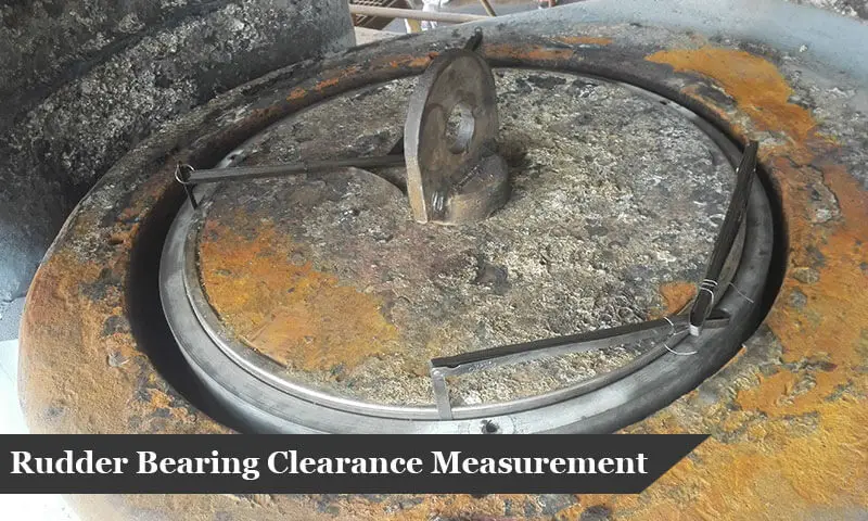
The rudder stock/pintle’s clearances and the bearing are recorded in the longitudinal direction (F-A) and the transverse direction (P-S). The clearance is typically recorded using feeler gauge or inside and outside micrometers whenever the rudder stock/pintle is dismantled and removed.
Initial (Minimum) Rudder Bearings Clearance
Maintaining the rudder bearing minimum clearance is vital to avoid jamming and bearing failure.
Bearing Minimum Installed Clearance is the sum of bearing running clearance, thermal expansion allowance, and absorption allowance. When the bearing is operating, the thermal expansion allowance will disappear upon reaching the maximum operating temperature, and the absorption allowance will disappear as the bearing gradually absorbs the lubricating fluid (for synthetic bearings). Running clearance will be the only clearance left.
Bearing minimum clearance will be clearly stated by the ship’s clarification society, calculating the clearance will slightly vary from one classification society to another. Bearing’s manufacturer recommended clearances should also be considered, especially when bearing material requires pre-soaking in association with the proposed method of lubrication.
Minimum installed clearance varies slightly depending upon the Classification Society as previously mentioned; however, we may calculate it based on the following formula: 0,001 D + 1 mm (Based on Bureau Veritas Rules), where D is the rudder stock/pintle diameter. The initial rudder clearance should not be less than 1.5mm for any diameter based on most classification societies’ requirements.
Maximum Rudder Bearings Clearance
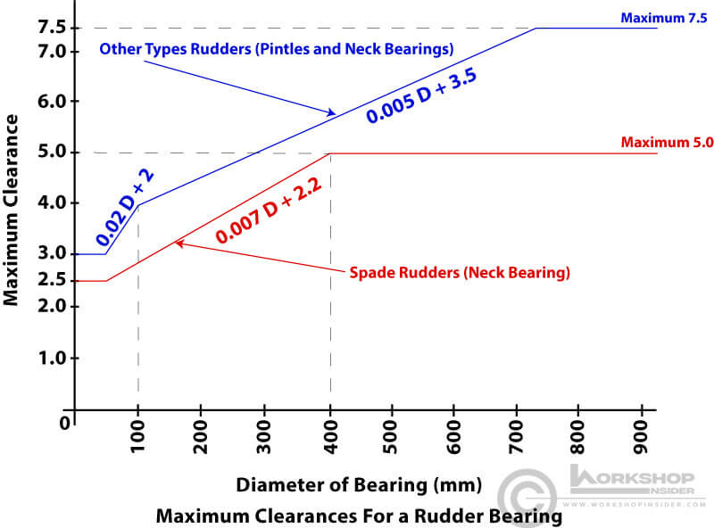
The maximum clearance for synthetic bearings should be following the manufacturer’s recommendations. Alternatively, the maximum clearance for both metallic and synthetic bearings should not exceed the classification society specified maximum clearance.
Similar to minimum installed clearance, the maximum clearances for rudder bearings vary slightly depending upon the Classification Society and the rudder arrangement. We can use the following graph to find the maximum allowable clearance (Based on Bureau Veritas Rules):
As a general rule, the maximum clearances for a rudder bearing can be calculated from the following formula: 5 + 0,002D mm (Based on Lloyd’s Register Rules), where D is the diameter of the rudder stock/pintle.
Rudder Bearing Replacement
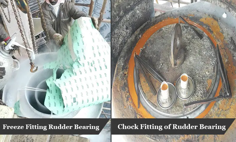
Whenever rudder clearance exceeded the maximum limits, the bearing then needs to be removed, followed by machining and fitting a new bearing. Rudder bearings are usually fitted using an interference fit. The fitting is done by either press fitting, freeze fitting, or bonding fitting.
An interference fit is sufficient to prevent bearing rotation under normal operating conditions in association with necessary stopper rings to prevent axial movement of the bearing. The amount of interference will vary based on the bearing’s size and with the minimum temperature at which it will operate. Additional interference is added for cold operation as insufficient interference for cold operations could cause the bearing to come loose in the housing.
Press Fitting
Fitting the bearing into the housing using pressing force. Small bearings can be easily pressed into the housing, while larger bearings fit easier with freeze fitting. The housing should not be heated, nor grease or oil be used to facilitate fitting.
Freeze Fitting
Freeze fitting is the easiest way to install rudder bearings, bearing contracts when cooled, thus facilitating easy fitting without expensive jacking or external forces. Using either liquid nitrogen or dry ice as a cooling agent for installations.
When using dry ice, it should be in a pelleted form or small pieces to make good contact with both the bearing’s inside and outside surfaces. The bearing should remain in the dry ice for a minimum of three hours and can then be checked to see if it has shrunk sufficiently for installation. If not, the bearing should be re-packed and checked in another hour.
For liquid nitrogen, the bearing should be completely immersed in a liquid nitrogen container. When vapour stops boiling off the liquid nitrogen after approximately 5 to 30 minutes (depending on the surface area of the bearing), the bearing has then reached to liquid nitrogen temperature of -196°C and can be installed.
Bonding Fitting
Bonding fitting is an acceptable alternative to interference fit whenever housing internal diameter is not machined, housing is not round or damaged by corrosion, or whenever the bearing thickness is thin to be fitted with an interference fit. Bonding fitting is done using either chocking compound or adhesive.
When using a chocking compound, the bearing is machined to the calculated inner diameter; the outer diameter should be calculated considering minimum allowed bearing thickness and minimum allowed thickness of chocking compound. The bearing is then installed in place with proper alignment followed by pouring the chocking compound. The bearing should not put in operation unless the chocking compound is fully cured.
Fitting the bearing using adhesive is like bonding the bearing into the housing; the thickness of the adhesive layer must be considered when dimensioning the outer diameter of the bearing.
Rudder Drop (Wear down) Measurement
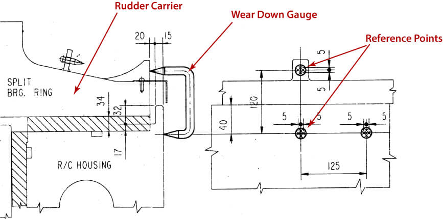
Rudder drop measurement is the wear down value of the rudder carrier bearing. A reference point is marketed on the rudder carrier housing, and another point is marked on the split bearing ring from the time of construction as per the following illustration.
The initial distance between the two reference points is measured and recorded when installing the steering system during the newbuilding using the wear-down gauge. During drydocking, the distance between the two reference points is measured using the same wear down gauge; the difference between the two measurements is known as the rudder drop value, or carrier thrust bearing wear down.
The position of reference points may vary between ships; however, the measurement principle is the same.
Rudder Jump Clearance
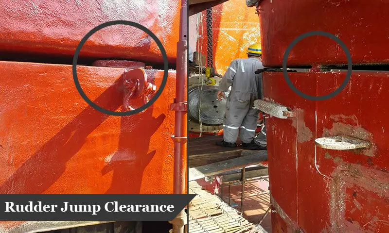
The jumping stoppers are solid bars fitting on the rudder and the stern frame (or rudder horn) in the port and starboard sides. The solid bars limit the rudder lifting due to the buoyancy effect or from movement.
The maximum jumping clearance should be less than the clearance between the steering gear ram and the tiller arm to prevent steering gear damage. Increasing jumping clearance could give an initial indication of excessive thrust bearing wear; thus, measuring rudder drop, in that case, is a must.
Rudder Ram-type Gear Clearances
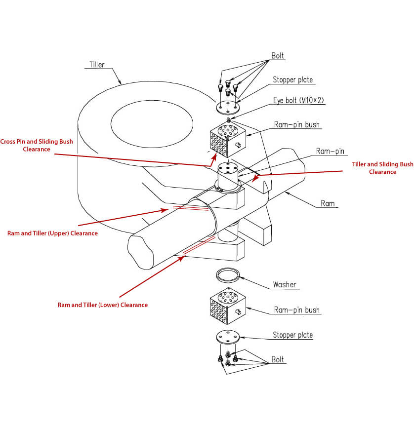
Ram-type gear clearances are the clearance between the crosshead pin and sliding bush and between the sliding bush and tiller arms. The clearances are taken to ensure a smooth transmittal of movement between steering gear rams and rudder stock. The recorded values should be compared to the maker’s recommended maximum clearance.
The other readings to be recorded are the clearance between the rams and the tiller arm; the clearance should be more than the jumping clearance to prevent steering gear damage due to the rudder lift.
Rudder Stock Trueness and Repairs
Verification of rudder stock trueness (straightness) is typically carried out whenever the rudder stock is removed for inspection. Whenever deformation is spotted, the stock straightening is performed by spot heating, pressing, or welding, depending on the stock size and the deformation shape.
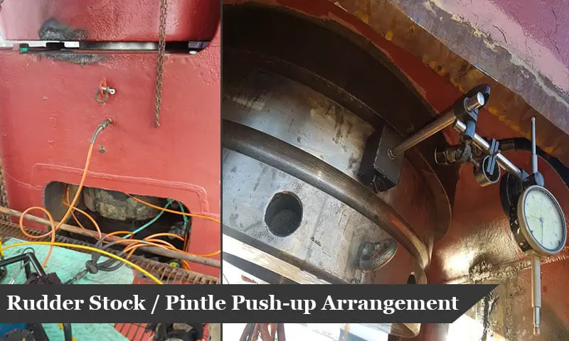
Before the final mounting of rudder stock, the contact area of the conical connection between the rudderstock and the blade/tiller to be verified by the Prussian blue test or a similar method. The contact between the conical connections should be a minimum of 70% as per most of the classification societies rules.
Rudder Blade Repairs
The typical rudder drydocking scope are stress cracks repairs and corrosion/cavitation pitting build-ups. Whenever cracks are found, they should be repaired by welding followed by rudder blade pressure testing. Corrosion/cavitation pittings are repaired by building-up the pitted points. Usually, a pressure test will not be necessary for pittings repair.
The rudder bottom plug is typically opened to check if there is water ingress inside the rudder. Whenever water is found inside the rudder, the root cause should be investigated and necessary repair to be performed, followed by pressure testing of the rudder blade.
References:

