A hydraulic motor is a mechanical actuator that transforms fluid power (hydraulic pressure) into rotational mechanical energy (torque) and angular displacement (rotation). A hydraulic motor can develop very strong torques, considering its small dimensions. Hydraulic motors are interchangeable with hydraulic pumps as they perform the opposite function. However, many hydraulic pumps cannot be used as hydraulic motors because they cannot be back-driven. In addition, hydraulic motors are designed to handle working pressure at both sides of the motor. In contrast, most hydraulic pumps rely on low pressure from the fluid reservoir at the input side and leak fluid when abused as a motor.
The applications of hydraulic motors are becoming more and more numerous. They are typically used whenever a slow or quick rotary movement with constant speed variations is required.
Hydraulic motor types
There are four basic types of hydraulic motors:
- Gear-type motors (internal or external gears).
- Vane-type hydraulic motors.
- Radial-piston-type motors.
- Axial-piston-type hydraulic motors.

They are characterized by:
- Their maximum rotational speed – Since hydraulic motors are volumetric devices, their speed will be more or less proportional to the adequate flow rate capacity of the supply pump.
- Their maximum operating pressure.
- Their displacement, which can be fixed or variable – Displacement is the quantity of oil the motor must be supplied with to achieve one shaft revolution.
- Their constant and peak power – Two types of power, power absorbed by the hydraulic motor, which depends on the flowrate capacity and the supply pressure, and power supplied by the hydraulic motor, which depends on the absorbed power and the output. The latter varies between 70 and 90 percent according to the type of motor, and losses are due to friction and leaking.
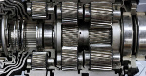
1. Gear-type hydraulic motor
The gear-type hydraulic motor consists of two gears, the idler gear, and the driven gear, that is attached to the output shaft. The high-pressure oil flows into one side around the periphery of the gears between the gear tips and the motor housing to the outlet port. The gears lock together, not allowing the oil from the outlet side to flow back to the inlet side.
The most significant advantage of the gear-type hydraulic motor is that catastrophic breakdown is less common than in most other types of hydraulic motors. This is because the gears gradually wear down the housing and main bushings, reducing the volumetric efficiency of the motor gradually until the motor is useless. This often happens long before wear causes the unit to seize or break down.
2. Vane-type hydraulic motor
A vane motor consists of a housing with an eccentric bore, which runs a rotor with vanes that slide in and out. The force differential created by the unbalanced force of the pressurized fluid on the vanes causes the rotor to spin in one direction.
3. Radial-piston type hydraulic motor
The hydraulic radial-piston type motor function is to transform the energy from the fluid pressure into rotational mechanical energy. The directional valve, a fixed and central part of the mechanism, is a quill shaft equipped with two lines, one for fluid intake and one for draining. The rotor turning on the directional valve is fitted with radial bores in which free-floating pistons operate.

A radial-piston type hydraulic motor organization is identical to that of a pump of the same type. It includes:
- Stator.
- Directional valve (fixed and central part of the mechanism).
- Rotor.
- Pistons (an odd number are installed in the bores of the rotor).
- Intake and delivery lines (installed on the directional valve).

The pistons in contact with the fixed track and rotated by the rotor have a reciprocating movement with respect to the rotor. To keep a motor torque constant, an odd number of cylinders is usually installed. The hydraulic fluid, pressurized by the pump, enters the bores and presses the pistons against the track of the stator for a half revolution. The following half revolution delivers the fluid into the drain line of the directional valve. Under the pressure load on the piston, the stator exerts stress on the piston, whose driving tangential component makes the rotor and the pistons rotate. This movement drives the output shaft of the motor. The systems are typically fitted with rollers to reduce the losses due to piston friction on the track.
A radial-piston type hydraulic motor, fitted with an eccentric stator is made up as follows:

This type of motor will provide only medium torque, but it may turn fairly rapidly because each piston requires only one volume of hydraulic fluid per revolution. By varying the eccentricity, we will be able to change the speed of the motor and obtain its reversibility for a constant flow rate. As the tangential force is exerted on a large lever arm (the radius of the stator), the torque provided will be very high. We will thus have a relatively slow-running motor with a very high output torque.
4. Axial-piston type hydraulic motor
For several years, axial-piston type motors, also called barrel motors, have been increasingly used in all fields, from public works to agriculture, industry, iron and steel production, aeronautics, etc.
Axial piston systems are suitable for heavy vehicle translations, which are pretty common in agriculture and public works. The main advantages are the following:
- High weight /power ratio.
- High rotation speed (up to 3,500 rpm).
- Operations under high pressure.
The axial-piston type motor includes a cylinder block including a certain number of axial peripheral bores (barrel), jointed pistons on a drive plate, and a plate directional valve with intake and output ports as per the following illustration:

As the drive plate has an angular position with respect to the barrel, the fluid intake in the cylinders causes the displacement of the pistons, which makes the drive rotate. For each cylinder, there is one phase of intake and of output per rotation. The piston is applied to the inclined plate with force proportional to the pressure. This force is decomposed into a force that tends to reduce the angle and into a force that tends to make the plate rotate.
The rotation direction of the drive shaft is linked to the inclination of the plate with respect to the axis of the barrel. On certain types of assemblies with axial pistons, it is possible to change this inclination. This means that the speed will vary for a constant flow rate, and a motor with two flow directions is obtained.
Two-flow direction motor
On the axial-piston type motors, the rotation direction of the drive shaft is due, but not solely, to the inclination of the plate with respect to the axis of the barrel. On certain types of assemblies with axial pistons, it is possible to change this inclination. This means that for a constant flow rate, the speed will vary, and we will obtain the change of flow direction of the motor as per the following illustration:

How are hydraulic motors classified?
Hydraulic motors are classified into two classifications: high-speed and low-speed hydraulic motors.
1. High-speed axial piston-type hydraulic motors
The high-speed motor category includes swash plate and in-line shaft units and angled axis units.

A. Swashplate and in-line shaft motor
The following illustration represents a swashplate and in-line shaft motor:

The drive shaft receives on its central splines the barrel, which includes nine bores containing nine pistons. When the motor is stationary, 4 to 5 pistons are pressurized. The delivery into the motor must overcome the resistive torque of the motor being driven. The torque resistance causes an increase in pressure in the piston chambers connected to the fluid intake port.
B. Angled axis motor
The operating principle is similar to the previous motor, only the position of the elements changes.

2. Low-speed hydraulic motors
Low-speed hydraulic motors have been designed not to exceed 300 rpm. This type of motor has been designed because it was necessary to obtain a low rotation speed and a high driving torque. The low-speed motor is thus a rotary device that transforms the hydrostatic energy from the pump into a rotary movement with high torque.
There are two main types of low-speed radial-piston motors:
- Outside cam motors.
- Inside eccentric cam motors.
Low-speed hydraulic motors are used for rotation and traveling for all types of merchandise handling machines, such as cranes, gantries, winch drives, mixer rotation, drilling machine rotation, etc.
The low-speed motor is different from the high-speed motor because it acts as a hydraulic reduction gear. It is thus able to transmit high torque without using mechanical reduction gears. For all low-speed motors, speeds of about one revolution per minute. The maximum speed limit of low-speed motors usually depends on the dimensions of the intake and delivery ducts in the receiver. Once a certain rotation speed is reached, the torque decreases. This fall is essentially due to the head losses in the supply ducts and the parts’ viscous torques rotating in the fluid.
A. Outside cam motors
The following illustration shows the construction principle of these new generation motors:

The above illustration is a motor with six outside cams and ten radial pistons. The difference between this generation and the previous one is essentially its power supply mode with the plane surface distributor. The intake and oil return pipes are connected to the distribution unit. Inside this unit, a circular ring (a) is linked to the intake, whereas a second circular ring (b) is linked to the motor’s oil return. Twelve equidistant ducts are alternately linked with the intake and return rings of the fluid.
The flat distribution plate has 12 holes and equidistant connection contacts through which the fluid will flow:
- Six holes for the intake of the pressurized oil coming from the distribution unit.
- Six holes for the oil return flowing towards the distribution unit.
- One oil intake hole, always followed by an oil return hole.
As can be seen in the following illustration:

When the piston is at the top of the cam, it is in a neutral position. At this moment, it is between two holes of the flat plate, and it is inactive. During its entire descent over half a cam revolution, the piston is linked with the oil intake hole and transforms the hydrostatic energy into rotational energy.
When the roller piston is in a cam hollow, it is in a neutral position again. At this moment, it is between two holes of the flat plate, and the piston is inactive. Over half a cam revolution, the piston is linked with the oil return hole during its entire return, and the oil is expelled into the reservoir.
B. Inside eccentric cam motors
Low-speed radial-piston motors are very common. They belong to the category of average pressure machines, which corresponds to about 200 bar.

The five cast iron pistons are radially installed and supported by the cam of the forged steel crankshaft. Each piston fits into the spherical end of a hardened steel connecting rod inside the piston housing. Each connecting rod is fitted with a small central duct which brings the fluid under pressure under the small end of the connecting rod. The crankshaft shaft is guided in rotation by two tapered roller bearings with wide dimensions enabling large radial thrusts on the splined shaft. The rotary distributor is fitted with different grooves on its periphery whose functions are as follows:
- Some receive the intake pressure by small internal ducts and ensure a radial balancing of the thrusts exerted on the distributor.
- Others are connected with the intake and the return of the main power supply circuit of the low-speed motor.
The operating principle is as follows. When the piston is at Top Dead Center, it is linked with the oil under pressure from a half-groove of the distributor. During its entire descent, the piston is connected to the intake. The hydrostatic energy is transformed into torque energy on the shaft employing the connecting rod supported by the crankshaft.
When the piston is at Bottom Dead Center, the distributor driven in rotation stops the oil intake for a short time. The oil intake duct in the casing is separated by the entire section between the two half-grooves of the distributor. After a 180 rotation, the piston-driven by the cam moves radially upwards. This is the fluid return phase.
The same duct in the casing can now be used to expel the oil. After a 360 rotation, the piston is at Top Dead Center, separated for a short moment by the entire section of the distributor grooves. It is ready to initiate a second operating cycle.
Advantages of low-speed motors:
When compared to high-speed motors, low-speed motors offer the following advantages:
- Good reliability due to the slow movement of the rotating parts.
- Low inertia for the moving parts enabling fast acceleration torques and inversions.
- Unaffected by external agents, they can work totally immersed without any problem.
Low-speed motor problems:
Low-speed hydraulic motor manufacturers have been confronted with various problems that they have tried to solve as follows:
- Because of their operating principle and because of the lack of sealing rings, low-speed hydraulic motors only provide an acceptable output once a certain rotation speed has been reached. Below this speed, leaks are considerable; the oil film can break, the motor functions by jerks and wears quickly, especially if the resistive torque undergoes large changes.
- To meet the work requirements and to obtain a high gear reduction combined with a low traveling speed, a combined hydraulic/power transmission assembly will need to be installed on certain equipment.
- If the motor has a low volumetric displacement, it will reach high speeds but will have low torque.
Related Article: Everything You Need To Know About Hydraulic Oil.
Hydraulic motors symbol
Like electric circuits, hydraulic circuits can be represented using symbols. Symbolic representation quickly identifies the type of motor which is present in the hydraulic circuit being examined.
Different types of hydraulic motors exist:
- Fixed displacement motors.
- Variable displacement motors.
- Reversing displacement motors.
Each of these motors can be represented by a symbol, making it possible to identify it precisely. The following illustration shows the different symbols for hydraulic motors:

References:
- Wikipedia Encyclopedia.
- Hydraulics and Pneumatics: A Technician’s and Engineer’s Guide.
- Essential Hydraulics: Fluid Power – Basic.
- Fluid Power: Hydraulics and Pneumatics.