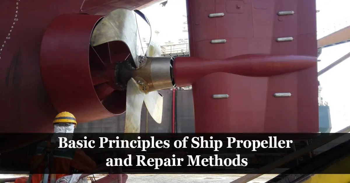
Propeller is the most component on ships and boats propulsion system; the propeller main converts the torque drawn from the main engine into useable thrust.
The propeller consists the hub which is the centre section of the propeller and the blades which are the fins connected to the hub. With a number of blades (three, four, five or even six) that set at an angle extending out from the hub which relates to the propeller pitch and directly measures and defines the output thrust.
As the propeller rotates ahead, the pressure increases at the face of the blade and is called Pressure Face, the opposite side of the blade is then called the Suction Face. The edge that cuts the water first is called the Leading Edge, and the opposite side edge is called the Trailing Edge.
The Tip is the most distant point of the blade outer edge from the hub, and the Root is the area where the blade joins the hub in FPP or the flange that contents to the hub in CPP.

Propeller Types
Solid Cast Propellers
Solid cast propellers are the most commonly used; it is also known as Fixed Pitch Propellers or FPP. The propellers are mostly made of cast Copper alloys or Stainless cast steel alloys which is less common and used for small vessels. Cast iron propellers are also fitted on small ships, but it is the least common type.
Solid cast propellers are either fitted on tailshafts with a key-way or keyless, keyless propellers are also frequent on large vessels.
Built-up Propellers
Built-up propellers blades and hub are cast separately and may be of different materials. The blades are oriented to the hub to produce the designed propeller pitch. Built-up propellers are practically no longer manufactured.
Variable Pitch (V.P.) Propellers
Variable Pitch propellers are also known as Controllable Pitch Propellers or CPP. Variable pitch propellers blades base are fitted on the propeller boss by a flange which is connected to the inner hub body. This mechanism allows propeller blades to revolve around the axis of their centre pin which gives variable pitches depend on the revolve angle. The mechanism is generally operated hydraulically.
Due to the ability to control the pitch of the propeller, the propulsion power can be entirely absorbed by the propeller under all loading conditions. In contrast with solid cast propellers, propulsion power is absorbed in a specific tonnage which was calculated during the design phase of the vessel.
The use of a variable pitch propeller requires that the propeller shaft be hollow. It is fitted to the propeller boss by a coupling flange. The forward end coupling flange can be removed to permit shaft withdrawal outboard.

Propeller Materials
Cast Copper Alloys
The commonly used grades of cast copper alloys are CU1, CU2, CU3 and CU4 depending on their chemical composition.
- CU1 (Manganese Bronze): Derived from 52~62 percent copper, 35~40 percent zinc, 0.5~4 percent of manganese, tin, lead, aluminium, iron and nickel, intended to increase the alloy’s resistance to corrosion. These alloys have tensile strengths up to 440 N/mm2.
- CU2 (Nickle-Manganese Bronze): Derived from 50~57 percent copper, 33~38 percent zinc, 3~8 percent nickel, 1~4 percent of manganese, tin, lead, aluminium and iron. These alloys have tensile strengths up to 440 N/mm2.
- CU3 (Nickle-Aluminium Bronze): Derived from 77~82 percent copper, 7~11 percent aluminium, 3~6 percent nickel, 0.5~4 of manganese, tin, lead, zinc and iron. These alloys have tensile strengths up to 590 N/mm2.
- CU4 (Manganese-Aluminium Bronze): Derived from 70~80 percent copper, 6.5~9 percent aluminium, 1.5~3 percent nickel, 8~20 of manganese, tin, lead, zinc and iron. These alloys have tensile strengths up to 630 N/mm2.
Stainless Cast Steel Alloys
The commonly used grades of stainless cast steel alloys are 12Cr1Ni, 13Cr4Ni, 16Cr5Ni and 19Cr11Ni depending on their chemical composition.
- 12Cr1Ni: Derived from 11.5~12.5 percent chromium, 0.8~1.5 percent nickel, carbon, silicon, phosphorus manganese, molybdenum, sulphur and iron. These alloys have tensile strengths of 540~690 N/mm2.
- 13Cr4Ni: Derived from 12~13.5 percent chromium, 3.5~5 percent nickel, carbon, silicon, phosphorus manganese, molybdenum, sulphur and iron. These alloys have tensile strengths of 760~960 N/mm2.
- 16Cr5Ni: Derived from 15~17 percent chromium, 4~6 percent nickel, carbon, silicon, phosphorus manganese, molybdenum, sulphur and iron. These alloys have tensile strengths of 760~960 N/mm2.
- 19Cr11Ni: Derived from 18~20 percent chromium, 9~12 percent nickel, carbon, silicon, phosphorus manganese, molybdenum, sulphur and iron. These alloys have tensile strengths of 440~640 N/mm2.
Cast Iron
The suitable cast iron used for propellers manufacturer that one contains nickel or silicon. Cast iron with nickel content reduces the effect of graphitic corrosion.
Graphitic corrosion is selective leaching of iron from grey cast iron, the iron get separated, leaving graphite grains intact while grey cast iron starts to deteriorate. Affected surfaces develop a layer of graphite and rust that inhibits further leaching reaction.
Cast iron form a rust layer which is brown and turns black when submerged in seawater. The rust layer does not readily flake off and provides corrosion protection to the underlying metal.
Propellers Stresses and Working Conditions
As the propeller rotates ahead, the thrust cyclic variations on the propeller’s face induce high stresses. The propeller tips move through the highest speed, causing tips to erode and become rough; as well, the propeller after few months of use, the polished surface disappears, and the propeller surface gets rough. The surface roughness creates cavitation, which causes erosion.
While the propeller is fitted and rotates, the propeller material is under tensile stress, which facilitates corrosion, and the combined effect of corrosion and tensile stress can create fatigue cracks. The corrosion effect in a bronze propeller has a minor effect on seawater, about 5/100 mm per year.

The corroded parts cause localized wear in the form of pitting, which is usually found on a radius above 0.5R on limited areas. The pitting can appreciably alter the propeller’s performance. Therefore, the pitting is usually smoothed out by grinding and temporarily repaired with a special mastic or compound.

The cavitation/erosion effect may form due to complex and variable flows. In certain spots (forward face), the seawater loses contact with the blades, and vapor bubbles are formed and then collapse. Their implosion involves heavy impact energy, which breaks up the metal’s surface and seriously erodes it. There is no method of preventing cavitation/ erosion from occurring on certain alloys, but the new hull design makes it less frequent.

The propeller blade aft faces up to 0,4R, including the connection with the hub, subject to moderate seawater strains. High strains are produced during significant cyclic variations of traction. However, these strains decrease rapidly in magnitude after 0,4R. The hub stresses produced in the bore are caused by the cone end fitting on the propeller shaft.
Propeller Repair
Propeller accidents or strikes against submerged objects may cause propeller damages, resulting in chipping, loss of metal, or even blade deformation. The most severe damage is the loss of a complete blade, thus making a propeller irreparable.

As a rule of thumb, small blade edge deformations are best left untouched or cut out, including a similar piece on the opposite blade to the correct propeller balancing if it is affected. However, a defect as a crack at the edge of the blade is never ignored as it may cause a rupture straight across the blade, significantly if it is sized above 25mm.
There are several methods to repair the propellers, such as:
- The straightening of the deformed blades.
- Arc or gas welding.
- Mould-casting.
Propeller Deformed Blades Straightening
The propeller repair by straightening is returning the blade to its original shape using hammering or minor pressing. The process requires an experienced repairer to perform this complex repair.
The final repair may be checked visually for minor repairs, or detailed checking of the final profile and match it with the propeller plans for complicated repairs.
For minor deformations at the blade’s tip, the repair is carried out by cold work under 200°C and with a press or hammer.
For larger deformations, the temperatures may be raised as follow:
- Manganese Bronze: 590-760°C for dynamic repair – Any temperature for Slow Pressure.
- Nickel- Manganese Bronze: 590-760°C for dynamic repair – Any temperature for Slow Pressure.
- Nickle-Aluminium Bronze: 760-950°C for dynamic repair – 760-950°C for Slow Pressure.
- Manganese-Aluminium Bronze: 790 – 870°C for dynamic repair – 700-810°C for Slow Pressure.
The temperature must rise slowly and be maintained using air/propane or similar gas blow torches.
When using pure oxygen, continuous moving the torch is essential to avoid any superficial surface spot fusion, which may cause cracks to form on cooling.
Upon completing the repair, cooling must be slow and gradual by covering the propeller with appropriate insulation.
Propeller Welding
Repair may be performed by welding to fill the pitting and re-melt the cracks. For a large portion missing of the propeller blade, a similar piece is cast and then joined to the blade by welding using proper welding procedure and necessary pre-heading and post-heating procedures.
Read more: Principles of Welding Repair of Propellers
Propeller Mould-casting
In this process, a sand mould is prepared on the propeller blade for the missing portion, with extra allowance considered for post-machining and grinding. This repair method is usually carried for the repair of manganese bronze or nickel-manganese bronze propellers. Suitable for repairing missing blade tips or fill-up of erosion and pitting; however, it cannot be performed on the hub due to distortion risks.
Finally, considering propeller working conditions and stresses based on the defect location is essential before repair execution; the precautions should be even greater, depending on the alloy from which the propeller is made.
Inspection after Propeller Repair
Propeller Pitch Measurement
The measurement requires that the propeller be mounted in a gravitational or another known plane, with a vertical pole installed on the shaft centerline. A rotating arm is fixed to the center pole, free to rotate in a plane parallel to the plane on which the propeller is mounted. From this arm, the various radii can be marked on the blade surface and drop heights to the blade surface measured at known intervals along the chord length.

The propeller blade section’s measurement is recorded, and it gets compared to the original design section. The pitch measurement is essential to verify that the propeller blade’s shape after the repair matches the original shape, and hence, the propeller pitch has not been affected.

Propeller Balancing
Propeller repairs may cause the propeller to be out of balance. The propeller will then experience out of balance forces that may cause severe damages, and therefore, the propeller has to be balanced before installation.
For large propellers (above 2.5m diameter), ISO 484/1 standard defines a requirement to conduct a static balancing. For smaller propellers (diameters between 0.80 and 2.50 m), ISO 484/2 standard defines the balancing requirement.
For the larger-diameter propellers, a static balance procedure is normally quite sufficient and will lead to a satisfactory level of out-of-balance force. However, for smaller propellers, which is usually operate at high rotational speed, dynamic balance is advisable.
Dynamic Balancing
The dynamic balancing is carried out by fitting the propeller on a dummy shaft and then mount them on the dynamic balancing machine; the machine rotates the propeller at its maximum operating speed and measures the weight of the rocking motion (unbalance). The machines give the unbalance weight and its angle and normally corrected by removing the specified extra weight.

Static Balancing
The propeller is fitted on the balancing fixture and then mounted on rollers. If the propeller is out of balance, the heaviest blade will swing down.
The excess weight on the heavy blade or blades will be removed by grinding. The grinding should be done on the propeller’s negative face and concentrate on the blade’s center and avoid edges. The process is repeated until all blades remain still regardless of the position the propeller is turned.


Reference:
– bureau veritas rules for the classification of steel ships
– International Association of Classification Societies