Welding repair of propellers is mandatory whenever defects found on the propeller surface due to damage caused by accident or defects associated with propeller manufacturing.
Whenever defects or cracks found on a propeller, grinding-off without welding is the preferred method, however, certain defects according to their size, severity and location will leave no option but to carry out repairs by welding.
The repairs by welding will be the option whenever the intended repairs increase the strength and the reliability of the propeller.
Propeller Materials
The propellers mostly made of cast copper alloys or stainless cast steel alloys which are less common and used for small vessels. Cast iron propellers usually fitted as well on small ships, but it is the least common type.
The propeller materials divided into several grades based on the material they are made of, as follow:
Cast Copper Alloys
The commonly used grades of cast copper alloys are CU1, CU2, CU3 and CU4 depending on their chemical composition.
Read more: Basic Principles of Ship Propeller and Repair Methods.
Stainless Cast Steel Alloys
The commonly used grades of stainless cast steel alloys are 12Cr1Ni, 13Cr4Ni, 16Cr5Ni and 19Cr11Ni depending on their chemical composition.
Read more: Basic Principles of Ship Propeller and Repair Methods.
Zinc Equivalent
The microstructure of CU1 and CU2 alloys comprises of alpha and beta phases. Toughness and resistance to corrosion fatigue characteristics of propeller material are highly affected by the proportion of beta phase on the material microstructure. The volume of beta phase increases with the increase of the zinc equivalent.
The increase of the zinc equivalent (beta phase) decreases the toughness and resistance to corrosion fatigue of propeller material and its weldability.
The zinc equivalent is restricted below 45% during propeller manufacturing, considering the possibilities of conducting repairs of propellers after their manufacture. The microstructure of CU1 and CU2 grade castings shall contain an alpha phase component of at least 25 % which indicates that the zinc equivalent is satisfactory.
The following equation defines zinc equivalent:

A microstructural examination conducted on casting grades CU1 and CU2 to determine the proportion of alpha phase on the specimen of the material. At least one sample is taken from each heat group, and the ratio of alpha phase shall be determined as the average value from 5 counts and should be at least 25 %.
Propeller Repair Zones
The propeller divided into three zones based on the effect of the defect and the associated risk of fatigue fractures following repairs. The zones designated as “A”, “B” and “C”.
Zone “A” is the zone subjected to the most significant operating stress; welding usually is not permitted at this zone. Hence, repair in this zone recommended performing it without welding. Welding is only allowed at this zone with special approval from the ship’s classification society; whenever welding carried out, it is necessary to be followed by stress-relieving heat treatment.
Zone “B” is the zone subjected to the high operating stress; welding is to be avoided wherever possible. Welding is allowed at this zone with pre-approval from the ship’s classification society.
Zone “C” is the zone subjected to the low operating stress; welding is considered safe at this zone. Welding is gets approved from the ship’s classification society whenever it is executed using an approved method and procedure.


Remarks:
- R: Radius of the propeller
- Cr: Length of the cord at radius R
- A propeller with a skew angle exceeding 25o is called a “Highly skewed propeller.”
- The surface of a fixed-pitch propeller hub and the controllable pitch propeller hub is classed as Zone “C”, except the areas of mounting the hub on the propeller shaft are to be classed as Zone “A”.
- The inner taper surface of a fixed-pitch propeller is classed as Zone “A”.
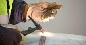
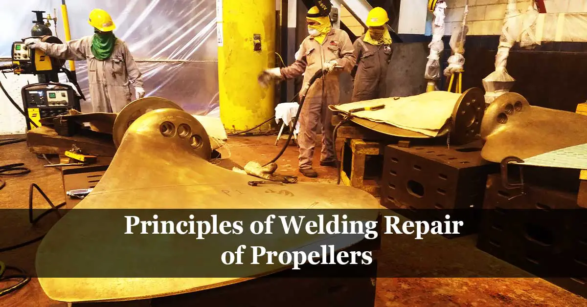
Propellers Repair by Welding
Manual arc welding is the most common welding technique for welding propellers regardless of their material; metal inert gas (MIG) is used. Also, tungsten inert gas (TIG) which used with extra care to avoid concentrated heat build-up. For casting CU1 and CU2 grades and where the material thicknesses are less than 30mm gas fusion welding method is used.
All propellers welded in a down-hand position (1G) after removing it from the propeller shaft.
Interpass temperature should be kept as low as possible to limit the risk of distortion and crack formation, particularly for casting CU3 grade.
A stress-relieving treatment has to be done for all repair weld to avoid stress corrosion cracking except for casting CU3 grade; stress-relieving treatment for casting CU3 grade will be applicable whenever significant repairs have to be carried out or where the filler metals used are susceptible to stress corrosion cracking.
Edge Preparation
The following sketches show the groove’s shape for building-up welding for an eroded portion and for a missing portion.

The following sketch shows the groove for the butt welding joint (U-shape); a V-shape joint is acceptable if the blade thickness at the welding part is 30mm or less.

The following sketch shows the shape of the groove of blowholes or cracks. The bevel angle has to be 30o or more and provide a corner radius of 6R or more at the bottom surface to allow the torch to reach the bottom of the joint properly.

Precautions to Be Taken During Propellers Repair
Preheating
The preheating temperature depends on the method and electrodes to be used. It can range from 150-425° C for manganese-bronze and nickel-aluminium bronze or from 40 to 150°C for nickel-aluminium bronze or manganese- nickel-aluminium bronze.
A surface more extensive than the concerned area by at least 300 mm all round must be preheated so that the temperature gradient is not greater than 55°C per 300 mm. These conditions must be maintained during the whole welding period.
In the fusion welding process, a preheat temperature of 260-320°C of the junction area must be reached before commence welding.
Stress relieving
Stress-relieving is essential to prevent the development of cracks due to stresses after the repairs.
Temperatures to be attained as guidance are:
- Manganese bronze 320 – 425°C
- Nickel-manganese bronze 370 – 425°C
- Manganese-nickel-aluminium bronze 450 – 510°C
It is usually not essential to immediately carry out stress-relieving after the repair; however, it is crucial that the heated part must be cooled slowly to ambient temperature.
For stainless cast steel alloys (12Cr1Ni, 13Cr4Ni, and 16Cr5Ni) except austenitic grades (19Cr11Ni), the castings shall be subjected to a post-weld heat treatment to its tempering temperature.
For casting CU3 grade, the alloy is relatively less subject to stress corrosion; therefore, stress-relieving treatment for this grade is not required unless in case of significant repairs or when using filler metals, which is susceptible to stress corrosion cracking.
References:
- DNV.GL – Materials for Propeller Fabrication.
- International Association of Classification Societies (IACS).
- Rules & Guidelines – Marine & Offshore – Bureau Veritas