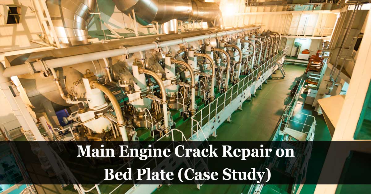
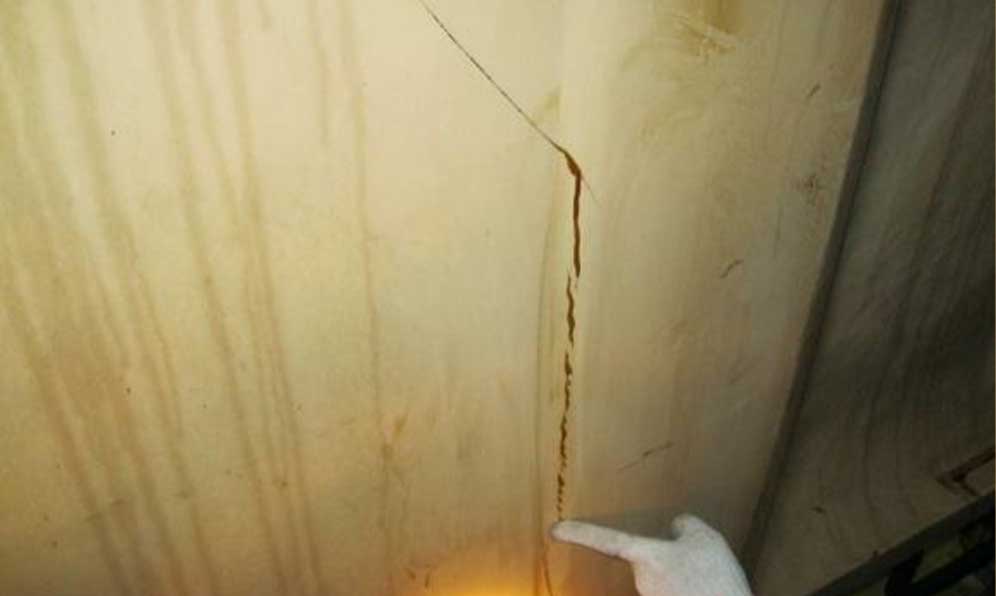
Main Engine crack repair project, One crack was found on the bedplate at main bearing no. 06, a crack appeared at weld seam connection between girder and transversal plate. The visible crack length was 1300mm.
(Crack overview)
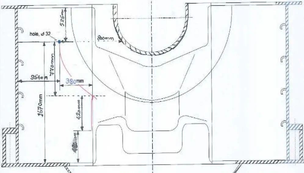
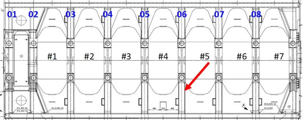
(Crack location, total lengths approximately 1300mm)
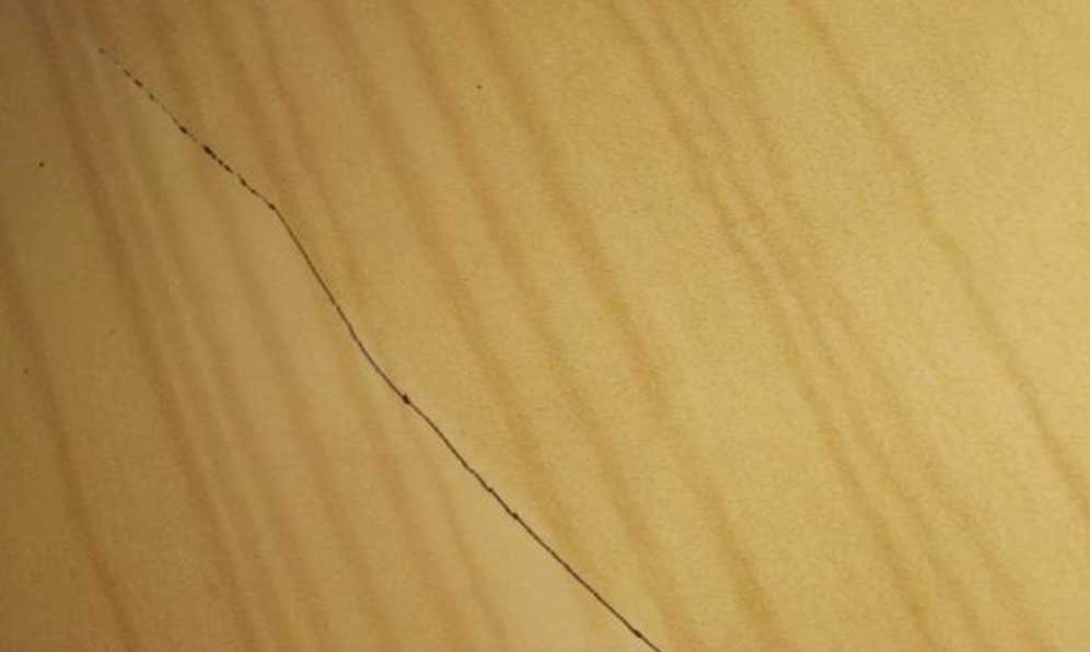
(Upper end of fracture)
(Lower end of fracture)
Pre-repair Preparation
Due to the repair procedure’s complexity, the repair was carried out under the maker’s service engineer supervision.
The preparations were:
- Tie rod tension was checked for the affected girder, and the foundation bolts close to the affected area.
- All crankshaft deflections were measured and recorded, and main bearing clearances on girder 4, 5 and 6.4
- The thrust bolts of girder no. 4, 5, and 6 were Slacken. And removed for girder no. 5 and also the side stopper next to them.
- The lower bearing shell was pulled out and stored outside of the engine.
- The radial distance circumferential was measured.
- The crankcase space of unit #4 and #5 was prepared for hot work. The work area was protected so that no sparks or dust will enter the unconcerned crankcase space, and measurement of crankshaft deflection during the welding work is possible.
Repair of girder no. 06
Main Engine crack repair was eliminated by installing insert plates.
Step 1: Open the Affected Transversal Plate
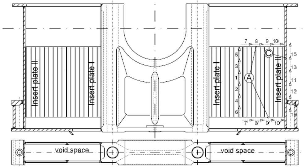
- On all four transversal plates, repair window (I) was installed.
- The height of the cutout area was decided based on the crack size.
- Existing weld seam was entirely removed by arc air, and the opening was ground smooth.
- The surface was ground smooth and checked by MPI to make sure the complete cracks were removed.
- The cutting area was checked by dye check and made sure all residuals were removed.
Step 2: Open and Repair Girder From Inside Of the Girder
- Tie rods no. 5 was slacken completely, then lift over the repaired spot and secured in position.
- A repair window was cut out in the cast girder.
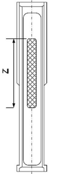
(Note: Dimension ‘Z’ was determined by the accessibility of the cracks from the tie rod tube)
- Crank web covered sections of the crack were opened from inside of the girder.
- The crack was opened, grooved by gouging, and ground smooth.
- The surface was ground smooth and checked by MPI, made sure the complete cracks were removed.
- Welding was carried out on a ceramic and copper backing to guarantee a good root surface on the tie rod bore.
- A welding sequence was implemented to avoid excessive residual stresses and allowing for free shrinking to the center axis of the engine.
- The opening was closed in the casting by cladding.
- Finally, the surface was ground smooth and check by MPI.
- Tie rods were lowered and tightened to full pretension.
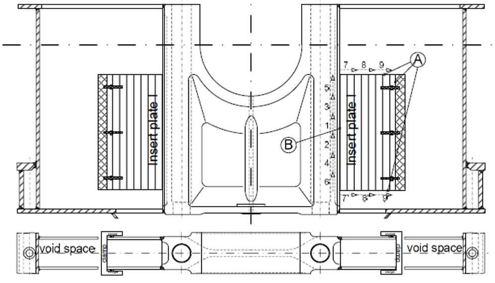
Step 3: Prepare Insert Plate (I) and Close Repair Window (I)
- The new insert plate no. I was prepared.
- The new plates were held in place using wedges and clamps, minimum every 300 mm.
1, 2, 3, 4, 5, and 6 Blocks were welded by pilgrim steps – root ground and re-welded.
7, 8, and 9 Blocks were welded by block welding technique.
- The new insert plate was welded.
- Welding sequence was used during welding.
- Welding sequence for the vertical/horizontal sequence was carried out with four welders simultaneously.
- All transitions were Ground smoothly
- The repair location was check by PT or MPI.
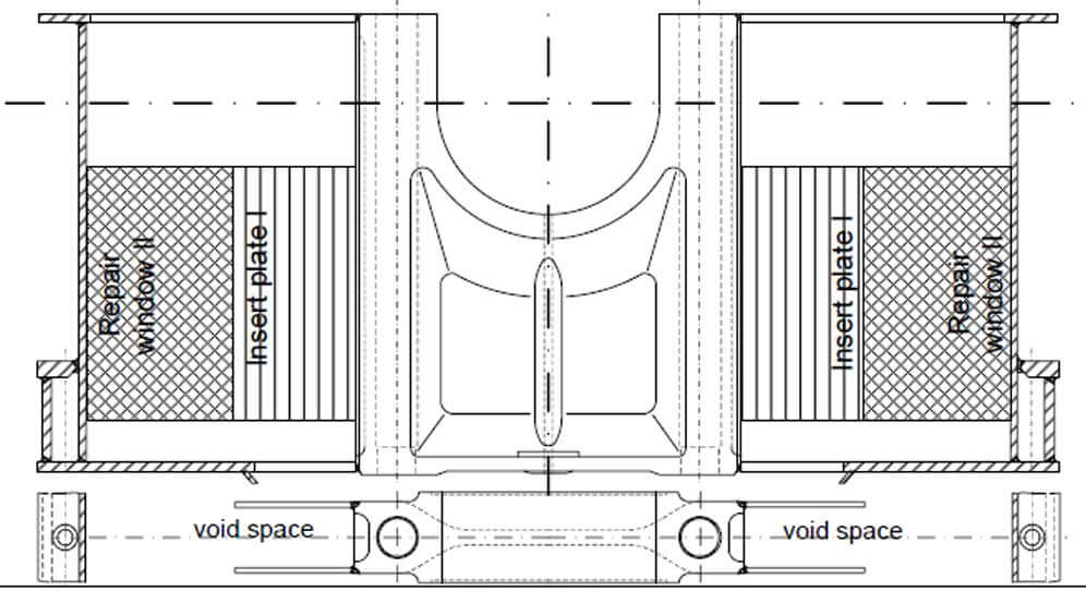
Step 4: Re-weld Between the Transversal Plates
- On all four transversal plates, a repair window (II) was installed.
- The existing weld seam was entirely removed by arc air and ground smooth.
- The whole space was checked by dye check and made sure the complete crack and all arc air residuals were removed.
- The root of the vertical and horizontal weld seam was removed until the possibility of lack of penetration is entirely removed.
- The vertical and horizontal weld was re-welded.
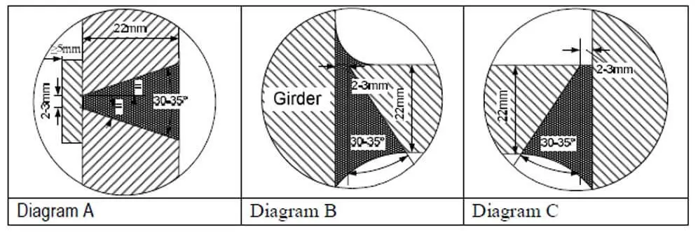
- A transition radius at the inside of the girder was made, according to (diagram B).
Step 5: Prepare Insert Plate (II) and Close Repair Window (II)
- The new insert plate was prepared (diagram A and C).
- The new plates were held in place by using wedges and clamps, minimum every 300 mm.
- The new insert plate was welded.
- Welding sequence was used during welding.
- Welding sequence for the vertical/horizontal sequence was carried out with four welders simultaneously.
- All transitions were Ground smoothly
- The repair location was check by PT or MPI.
Preheating up to 60° C minimum was applied before welding was started
The interpass temperature was strictly observed and controlled not to exceed 150 °C
Only small welding rods Ø 2.5 mm was used
STAW (111) and FCAW process (136) were used
Step 6: Stress Relieving Shape
- A release shape was cut as below.
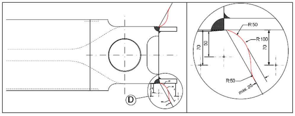
- Grind the transition smooth.
- The surface was ground smooth to the remaining opening in the longitudinal direction (to reduce transversal cuts through the plate thickness).
- All kinds of carburized and hard spot material were removed.
- First step: used paper grinder, grid 80.
- Second step: used paper grinder, grid 120-180.
- Third step: used final paper grinder, grid 240 (surface quality N9).
- All surfaces were checked by PT or MPI.
- The complete welding repair were checked with UT and MPI.
- All removed engine parts were reinstalled.
Foundation Verification
- The existing resign chock was checked.
- A round hole in the tapered plate (16mm thickness) with Ø 120mm was cut, and a feeler gauge was used to measure the clearance.
- We were ready to break the whole adjacent orange resign chock and replace it with a new one if a gap appears (was not needed in our case).
- Afterwards, the round opening was closed and ground smoothly.
Bearing Seat Verification
- To verify a proper contact between the machined bearing seat and the new bearing shell, an oversize bearing shell was ordered in advance.
- Study the measured results and the jack-up test to decide if the bearing seat machining is required (was not needed in our case).
Main Engine Crack Repair Final Checks
- A jack-up test for calculating the main bearing loads as a reference before and after the repair.
- After finishing the repair, the bedplate was checked at constant intervals for main bearing damage signs.
Welding Equipment Used on the Project
- General welding equipment.
- Gas burner (flame cut).
- All-position gas cutting machine for straight-line cutting.
- Gas burner for preheating.
- Arc air torch ø 6mm and Ø 8mm and arc air units 500 Amps.
- DC welding units with remote control.
- Welding rods acc. to AWS-ASTM: E 7018 and ISO E 51 5 B 110 20, ø 2.5mm.
- Welding units for FCAW with remote control.
- FCAW filler wire Æ 1.2mm, AWS A5.20; E71T-1, (CSF-71T)).
- Shielding gas EN 439, M2I.
- Drying furnace for the rods, two heated electrode holders.
- Pneumatic angle and normal grinding machines of several sizes, ø 125mm and ø 175mm (grinding disc thickness 2.5 and 6mm).
- Grinding turbines for hard metal cutters.
- Grinding turbines for stones ø 25mm and ø 60mm.
- Big pneumatic hammers with chisels for peening of the welding layers.
- General hand tools such as hammer, chisels, files, angle, ruler, etc.
- General illumination material for repair area.
Main Engine Crack Repair Duration
The repair job was completed in 14 days.
Related Article: Engine Crank Web Deflection Measurement.
Interesting Article: Top 50 Mechanical Engineering Blogs, Websites & Influencers in 2021.