When you hear the word ‘welding,’ the image that comes in front of your eyes is a welding arc acting on the workpiece metals to melt and fuse them into a weld joint. However, friction welding is solid-state welding, and there is neither an arc nor any melting of the metals. The commercial use of friction welding was introduced in 1960 in the USA.
This article takes you through different aspects of friction welding such as, what is the principle of friction welding and how it works, types of friction welding processes, equipment or machine used in the friction welding process, how strong is friction welding, advantages and disadvantages of the friction welding process, application of friction welding process and safety considerations.
What is the principle of friction welding, and how it works?
We often rub our hands together during cold weather, and as you increase the rubbing speed, your hands become warm. This happens due to the mechanical friction and the force you apply during rubbing. Imagine what happens if two metallic objects are rubbing against each other at high speed with applying pressure to the metallic objects. Yes, you are correct; it leads to generating a large amount of heat at the interface. Friction welding uses this heat to forge a joint (coalescence) of the two metals at the interface, and the pressure used depends on the metals to be joined. This is the principle of friction welding.
Friction welding is solid-state welding since the welding of two metals happens when both are in solid form. Since there is no melting involved in friction welding, the weld joint can be better described as a ‘forge welding.’ So, you can define friction welding (FRW) as a solid-state welding process, and the welding happens under pressure and using the heat generated by friction.
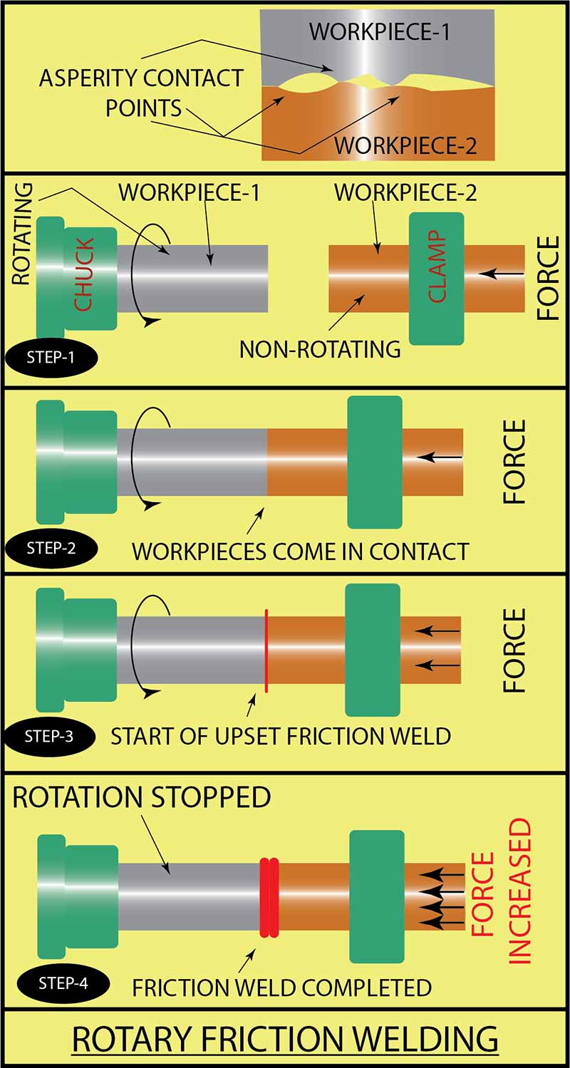
One of the main prerequisites for friction welding is that the workpieces to be joined must have a square and machined smooth surface. When we see a machined surface with our naked eye, it appears smooth, however, in reality, the smooth surface contains very tiny projections, and these projections are called asperities. When two metallic workpieces move relative to each other (rubbing), the asperities at the interface surfaces interact, and friction is generated (due to resistance to the relative motion). Interaction between the asperities at the interface generates frictional heat. The heat generated causes the metals to soften (plastic condition). When in softened condition, the axial pressure applied on the workpiece metals mixes the metals to create the bond or weld.
The process parameters of the FRW process
This process has three factors or parameters:
- The rotational or reciprocating speed: The rotational or reciprocating speed depends on the metal to be welded and the contact area at the interface.
- Pressure: The amount of pressure applied on the workpieces (both at the initial and finishing stages) depends on the speed of the moving workpiece, type of metal, and the cross-sectional area of the workpiece metals.
- Welding time: The welding time depends on the speed of the moving workpiece, type of metal, the pressure applied, and the cross-sectional area of the workpiece metals.
Types of friction welding
There are different FRW processes, and each one of them works differently. However, the basic working principle and the requirement remain the same, and it is explained below.
Both the workpiece metals should be prepared so that they have a smooth and square surface. The workpieces are mounted on the machine, one will be stationary, and the other will have movement (the movement can be rotary or reciprocating). The moving workpiece rotates or reciprocates at high speed. In the beginning, the two workpieces make contact at the interface, and at this stage, a little pressure is applied to the workpieces. This cleans the interface surfaces by burnishing action.
Now, the pressure on the stationary workpiece is increased, and it is forced toward the rotating or reciprocating workpiece. This results in the generation of high frictional heat at the interface (contact surface). This is continued till the plastic formation state is achieved. When the plastic formation happens at the contact surfaces, the rotary or reciprocating movement is stopped, the workpieces are held under pressure till the weld joint forms. The pressure can be increased if necessary.
The different types of friction welding processes are:
- Rotary friction welding.
- Inertia friction welding.
- Linear friction welding (LFW).
1. Rotary friction welding (RFW)
As described in the above illustration, rotary friction welding is usually done by mounting the workpiece metals on a horizontal axis. However, there can be machines doing this on a vertical axis also. The rotary FRW happens in the following steps:
- One workpiece metal is held in a chuck or collet and is rotated at a constant high speed. There will be a provision to disengage the chuck from the drive motor.
- The second workpiece metal is firmly held stationary, and the machine has provision for moving this workpiece towards the rotating workpiece and also apply axial pressure.
- Initially, the low contact pressure is applied on the workpieces to bring them into contact and clean the surfaces by burnishing.
- The pressure is increased, and frictional heat is generated at the interface of the two workpieces.
- Once the heat generated is sufficient for FRW, the rotary motion of the workpiece is stopped, and the pressure is maintained or increased to complete the welding.
- A forged joint forms at the interface (faying surfaces), and a part of the softened metal squeezes out to form a flash. The flash can be machined off.
- The two workpieces must remain on the same axis throughout the friction welding process.
- The flash can be minimized by controlling the welding parameters.
Friction welding has been used for welding steel bars up to 100 mm diameter or more and pipes up to 100 mm outside diameter. Rotary FRW is used for welding copper aluminum electrical connections, turbine shafts, piston rods, automotive axels, cutting tools, etc. Generally, the workpieces have a round cross-section. However, one of the workpieces may have a different cross-section.
The friction welding can be inspected visually. The formation of a flash on the periphery of the workpiece occurs during welding, and the amount of flash depends on the weld metals and weld parameters. A flash that sticks out quite straight from the joint may indicate a very high speed or low pressure, or lower welding time. A flash that curls much backward from the weld joint indicates a very high welding time and a very high welding pressure.
2. Inertia FRW
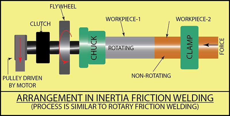
Inertia welding is a modification or variation of rotary FRW, and the process is similar to rotary FRW with one change. The chuck (on which the rotating workpiece is clamped) is mounted on a shaft that has a flywheel. The flywheel rotates along with the chuck and the rotating workpiece, and there is a provision to disengage the flywheel from the motor. Inertia FRW happens in the following steps:
- One workpiece metal is held in a chuck and is rotated at a constant high speed. A flywheel is mounted behind the chuck (on the same shaft).
- The second workpiece metal is firmly held stationary, and the machine has provision for moving this workpiece towards the rotating workpiece and also apply axial pressure.
- The stationary workpiece is brought in contact with the rotatable workpiece. The rotatable workpiece starts rotating, and when it attains the specified speed, the flywheel is disengaged from the motor.
- The flywheel (hence the rotating workpiece) continues to rotate due to the mechanical energy stored in it.
- The pressure is increased, and frictional heat is generated at the interface of the two workpieces. The heat generated is sufficient for friction welding, and the pressure is maintained or increased to complete the welding.
- A forged joint forms at the interface (faying surfaces), and a part of the softened metal squeezes out to form a flash. The flash can be machined off.
- The FRW is completed by the time the flywheel stops.
- In this process, the kinetic energy (rotational energy) stored in the flywheel is converted into frictional heat.
- The conditions required for inertial welding can be standardized and duplicated with ease; hence the quality achieved by inertia welding has consistency. Inertia welding can be automated.
The heat-affected zone (HAZ) for inertia welding is narrow because of the short time heating and cooling. All these make inertia welding a preferred process. The key factors in inertia welding are the flywheel mass, rotation speed, and axial pressure applied.
Advantages of inertia FRW
- Reduction in cycle time.
- Very good consistency.
- Repeatability.
- Welding of dissimilar metals saves cost since the quantity of costly metal used will be less.
Limitations of inertia FRW
- The weld metals should be ductile at FRW temperatures.
- Only butt welding is possible.
3. Linear friction welding (LFW)
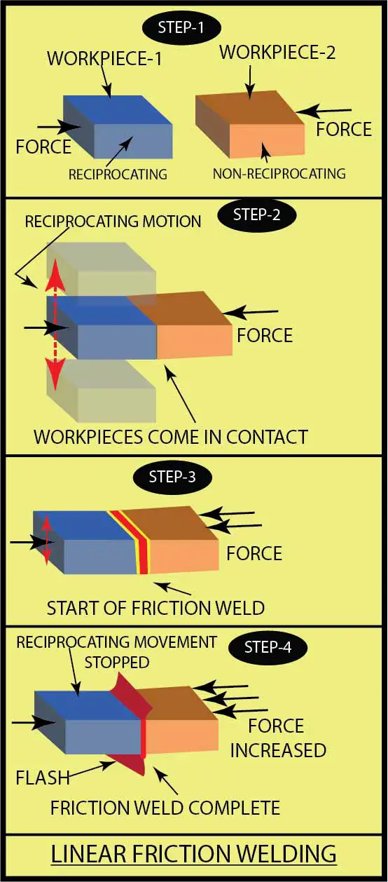
Linear friction welding machines can be of vertical or horizontal construction. Linear FRW is similar to rotary FRW and can be explained in the following steps:
- One workpiece metal is firmly held in a fixture and can be moved towards the other workpiece, and there is a provision for applying pressure. The second workpiece metal is mounted in a fixture and has a fast reciprocating movement.
- The stationary and the reciprocating workpieces are brought into contact, and they start rubbing against each other at the interface. This rubbing action removes the contaminations at the interface (faying surfaces).
- The pressure on the workpieces is increased, and due to the fast reciprocating movement and pressure, sufficient frictional heat is generated at the interface.
- The reciprocating movement of the workpiece is stopped, and the pressure is continued (or increased if necessary) till the workpieces get forge welded.
The LFW process is normally used for joining metals, but even plastics and wood have been joined using this process.
Application of LFW
- Blade integrated disks (blades and disks from a single piece) or BLISKS, in short, can be manufactured using the LFW process. The blades can be joined or integrated with the disk by using a linear FRW process.
- LFW process is used for joining metals for aircraft structural components.
- In the above FRW processes, the length of the two workpieces will get shortened in the direction of the pressure due to burn-off, and this metal comes out of the interface as a flash. Any oxides, foreign particles, and contaminants that come out along with the flash and the weld joint will be pure metal. The two workpiece metals will become very hot and plastic forms but remain solid throughout the FRW process.
Variations of friction welding
The different variations of FRW are:
- Radial friction welding.
- Orbital friction welding.
- Friction surfacing.
- Friction stir welding.
1. Radial FRW
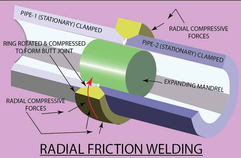
Radial friction welding (RFW) is a variation of the friction welding developed to join two long pipes. In conventional friction welding, one pipe length needs to be rotated to general frictional heat. However, in RFW, both the pipes remain stationary. One end of each pipe is made ready for full depth V-groove butt welding or 3/4th depth. V-groove butt welding. The two pipe lengths are firmly held butting against each other, and a solid beveled ring is pushed over the V-groove preparation. The technique followed is:
Rotate the beveled ring at high speed and apply radial pressure on the ring. To prevent the collapse of the weld joint and weld metal purging into the pipe bore, a solid or collapsible mandrel can be inserted (into the pipe) at the weld joint. The rotating solid beveled ring and the interface of the two pipes become plastic and soft due to the frictional heat, and the radial forces push the solid ring into the V-grove, and the welding is completed.
2. Orbital FRW
The orbital friction welding is similar to the rotary friction welding process; however, in this process, both the workpieces rotate in the same direction at the same speed, but their axes are offset (around 3 mm). The two workpieces are brought into contact under pressure.
When sufficient frictional heat is generated and the faying surfaces are in plastic. Soft condition, the rotary motion of the workpieces are stopped, the workpieces are brought to the same axes (common axis of the machine). The workpieces are friction welded by maintaining the same pressure or increase it if necessary.
The method of orbital welding can be used for rotary as well as linear friction welding. Orbital friction welding helps to weld non-round workpieces.
3. Friction surfacing
The process of friction surfacing is an offshoot of friction welding, and using this process, a coating of the required material can be applied on the base metal (substrate). Here a rod of the coating material is in contact with the base metal and rotated at high speed and pressure. Due to the frictional heat, the coating metal turns into a plastic state and gets coated on the base metal. The rod (of the coating material) moves along the base metal surface and coat the required area.
Note: These friction welding variations may still be in a developmental stage and yet to be commercialized.
4. Friction stir welding
Friction stir welding (FSW) is a variant of the FRW process; the reason for the development of FSW is explained below:
Some of the aluminum and its alloys (2024, 7050, and 7075) are difficult to weld by friction welding process since they have brittle dendritic structure and microporosity and poorer mechanical and fatigue properties. The said metals also suffer a loss of alloying elements from the weld pool and loss of strength in the heat-affected zone. To overcome the problems, one of the methods used for welding the aluminum alloy is stir welding (other methods are electron beam welding and laser beam welding).
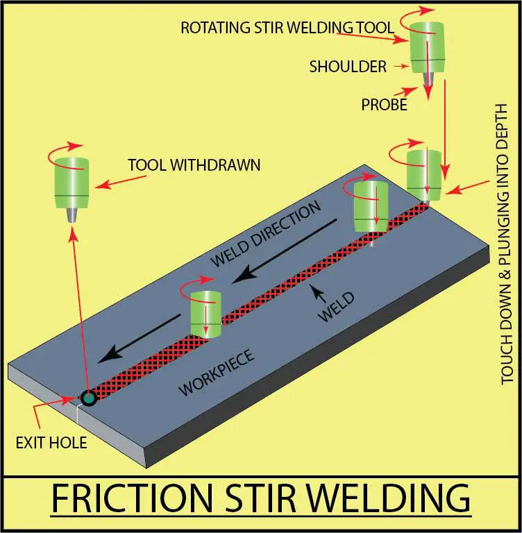
Friction stir welding (FSW) uses a non-consumable tool for generating frictional heat and welding. The non-consumable tool rotating at high speed is plunged into the interface of two workpiece metals. The rotating tool moves through the interface, and the frictional heat generated at the interface of the workpiece metals makes them plastic and soft at the interface. The rotating tool mixes the two metals and forms a weld joint.
Friction stir spot welding (FSSW) is an application of friction stir welding, and here the non-consumable rotating tool plunges into the two workpiece metals arranged for the lap joint and makes a spot weld. Once the spot welding is completed at one location, it can move to the following location.
Process parameters of FSW
- Rotational speed.
- Travel speed.
- Shoulder profile.
- Pin profile.
- Relative sizes of pin and shoulder.
- The material of pin and shoulder.
- Insertion angle.
- Preheat/cooling.
- Plunge depth.
Advantages of friction stir welding (FSW)
- Solid-state welding process. Low heat input.
- Generally used for welding of 20XX, and 70XX, and similar aluminum alloys.
- A fine-grained recrystallized microstructure weld can be achieved.
- No major change in chemical composition.
- Lower power consumption.
- It can be used for a wide range of metals.
- Increased productivity for thicker sections (more than 10 mm).
- It can be used for straight welding and also circumferential seam (butt) welding of pipes.
- Flash-free welds.
- The process can be automated.
Limitations of friction stir welding (FSW)
- Solid and rigid fixtures are required to hold the workpieces firm during welding.
- End hole is created (development is underway to eliminate this problem).
- The process cannot do filler welds.
- The process needs sophisticated equipment, is not portable, and requires automation.
Application of friction stir welding (FSW)
- The aerospace engineering-Wings, cryogenic fuel tanks, aircraft body or structure, and aviation fuel tanks.
- The marine engineering-Floors, deck panes, hull, other structures, refrigeration plants, and other frameworks.
- Railways-Railway tankers, high-speed train coaches, goods wagon, and container bodies.
- The automotive engineering-Chassis and body, wheel rims, bicycle and motorcycle frames, fuel tankers, armor bodies, etc.
- Other industries-Construction of bridges, reactors for power and chemical industries, air conditioners, food tins, bus bars, etc.
Comparison of friction stir welding with fusion welding:
| No |
Friction welding |
Fusion welding |
| 1 |
The appearance of the weld |
|
| Smooth | Not so smooth or rough | |
| 2 |
Distortion of the workpieces |
|
| Very less (negligible) | Sometimes very significant. | |
| 3 |
Consumable and shielding gas |
|
| Not required. | Required. | |
| 4 |
Environmentally friendly? |
|
| Yes | No | |
| 5 |
Thermal radiations and harmful fumes? |
|
| No | Yes | |
| 6 |
Cost of equipment |
|
| High | Low to moderate for most of the fusion welding processes. | |
| 7 |
Resistance to corrosion |
|
| Good | Not as good as friction welding | |
| 8 |
Cost of welding |
|
| Moderate | High | |
| 9 |
Welder safety |
|
| Welder is not exposed to thermal radiation and harmful smoke. | Welder is exposed to thermal radiation and harmful smoke. | |
Equipment or machine used in the friction welding process
The equipment for friction welding depends on your need. If you need only a small batch of friction welded parts, then you can think of using one of your old machines in the workshop for friction welding. Consider your old lathe machine; it has a revolving chuck or collet for holding the revolving workpiece. The other workpiece can be held in the tailstock. For friction welding of small diameter rods (less than 10 mm), you can apply the axial pressure by manually turning the tailstock handwheel. Your lathe has the provision to stop the rotary motion at any time.
For medium size (diameter) rods, you may have to get one special fixture made and mount it in the place of the tailstock. This special fixture will have an arrangement to firmly hold the stationary workpiece and move it towards the rotating workpiece with hydraulic pressure. The maximum diameter of the workpiece that can be friction welded depends on the size and rigidity of the lathe machine. Similarly, a milling machine can also be used for friction welding.
Note: Before doing friction welding on a lathe or milling machine, study your machine condition, discuss with the operator who works on the machine, and then decide what is the maximum diameter you can safely friction weld.
If you have a CNC vertical machining center, you can discuss with the machine manufacturer if it can be used safely for friction stir welding without disturbing its accuracy. However, for manufacturers whose production requirement is high, and requires consistent quality and productivity, dedicated friction welding machines are available in the market. Some of them are briefly explained below.
CNC controlled rotary FRW machine.
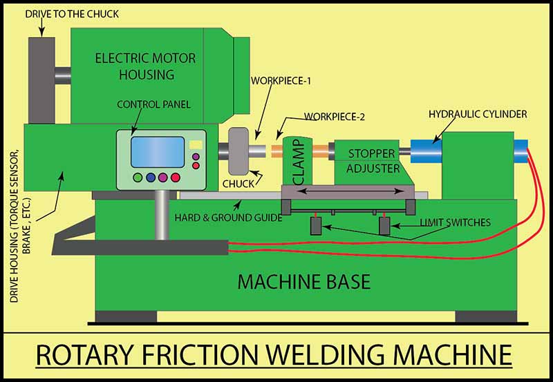
The left side of the machine has the drive arrangement and has a collet for mounting the workpiece that rotates. The right side of the machine has self-centering clamps for firmly holding the non-rotating workpiece. The non-rotating workpiece will be moved towards the rotating workpiece.
The machine has a CNC (Computer Numerical Control) system, and a program can be fed into it. The machine has provision for applying the hydraulic pressure. The machine has all high-tech features like servo motors, ball screws, etc. The machine has a built-in unit that machines of the flash immediately after the resistance welding is completed. There can be a robotic hand for automatic loading and unloading of the workpieces. Clean workpiece comes out of the machine duly friction welded and flash removed.
Dissimilar metals that can be joined are steel and stainless steel, copper and stainless steel, aluminum and stainless steel, aluminum and copper, aluminum and aluminum, and copper and copper. The machines can have a nominal forge load of 8 to 125 tons. The welding capacity ranges from 4 mm diameter to 145 mm diameter (for the sake of specification, the material considered is mild steel).
The manufacturer can build machines with special features like a double spindle rotary friction welding machine that can friction weld workpiece-1 and workpiece-3 to the centrally clamped workpiece-2 simultaneously.
Friction stir welding (FSW) machine
You can go for a dedicated CNC-controlled FSW machine if your production requirement is very high. The CNC FSW machine will look like a vertical machining center and works similarly, with the only exception that it welds instead of machining.
There is another option. If you already have a vertical machining center (3, 4, or 5 axes), you may explore and go for a friction stir welding head adaptable to your CNC machine. This will enable you to change over to machining head and use your machining center for machining or change over to FSW head and use your machining center for friction stir welding.
Linear friction welding machines
The construction of the linear friction welding machine can be horizontal or vertical. The machine features can be similar to the rotary friction welding machine, except that one of the workpieces has reciprocating motion instead of rotary movement.
How strong is friction welding?
In most friction welding processes, the strength of the weld will be equal to or more than the strength of the weaker of the two workpiece metals being welded. It is essential to adhere to the specified welding parameters to achieve consistency in strength.
People have conducted various tests like tensile and bending on the friction welded parts, and it is noted that the failure of the part took place in the parent metal and not the friction weld. This strongly supports our initial statement, “the strength of the weld will be equal to or more than the strength of the weaker of the two workpiece metals being welded.”
Friction welding is used for welding two ductile metals or a ductile metal with a hardened metal or other combinations. The weld joint formed by welding two ductile metals and ductile metal with a hard metal will not be having the same strength.
Advantages and disadvantages of the friction welding process
Advantages:
- Friction welding does not need filler metal, flux, and shielding gas.
- The process is environmentally friendly since it does not generate harmful radiation, gasses, and smoke.
- The friction welding happens in a solid-state, and there is no molten weld pool.
- The oxides formed can be removed after welding.
- This process has narrow heat-affected zones.
- In most of the welds, the strength of the weld will be equal to or more than the strength of the weaker of the two workpiece metals being welded.
- Friction welding can be automated for mass production.
- This is an efficient and comparatively fast process.
- The equipment required is minimum, and it is possible to weld a wide variety of ductile metals and their combinations.
- The setup can be created in-house by modifying the existing lathes or milling machines; however, dedicated equipment is required for consistent quality and fast production.
Limitations:
- Non-forgeable (not ductile) metals cannot be friction welded. This process requires that one of the two workpiece metals be ductile when hot to allow plastic deformations.
- Preparation of the workpiece surfaces and their alignment can be critical for developing uniform friction and heating, especially for workpieces of less than 50 mm diameter. One workpiece is rotating at high speed, and the other is stationary, and they must be adequately aligned.
- Dedicated specialized friction welding equipment and tooling for a higher production rate and more increased process capabilities will be costly.
- Difficult to rectify defective welding.
- Equipment is not portable.
Application of FRW
- Friction welded parts are used in various engineering industries viz. aerospace, agricultural, automotive, oil and refinery, defense, marine, shipbuilding, etc.
- Different automotive parts that are friction welded are gears, axle tubes, drive parts, shock absorbers, hydraulic piston rods, bushings, etc.
- Friction welding is widely used in the electrical industry for joining aluminum and copper.
- Friction welded stainless steel parts are used in marine engineering, pumps for domestic use, pumps used in chemical and food processing industries, etc.
- Many times expensive forgings and castings can be replaced with friction welded assemblies.
Safety considerations
In one way, friction welding is safer for the welder than other welding processes since there is no welding arc, no thermal radiation, or harmful smoke. However, friction welding (specifically friction stir welding) has workpieces or tools rotating or reciprocating at high speed, and they are hot. There is always the danger of entanglement of the welder apparel with the moving parts. The welder should not wear any loose or hanging type of apparel and must wear his shoes and gloves. The machine must have guards which should cover the machine during the friction welding process.
Conclusion
Unlike the fusion welding processes, friction welding is comparatively a recent addition to welding processes. Friction welding is solid-state welding and is environmentally friendly. Presently there are many friction welding processes under development. All these make friction welding the welding process of the future.
Interesting Article: Everything You Need To Know About Cold Welding.
References:
- TWI Global website.
- Stir weld website.
- American Friction Welding.
- Friction Welding: Thermal and Metallurgical Characteristics, Book by Ahmet Z. Sahin and Bekir Sami Yilbas.

