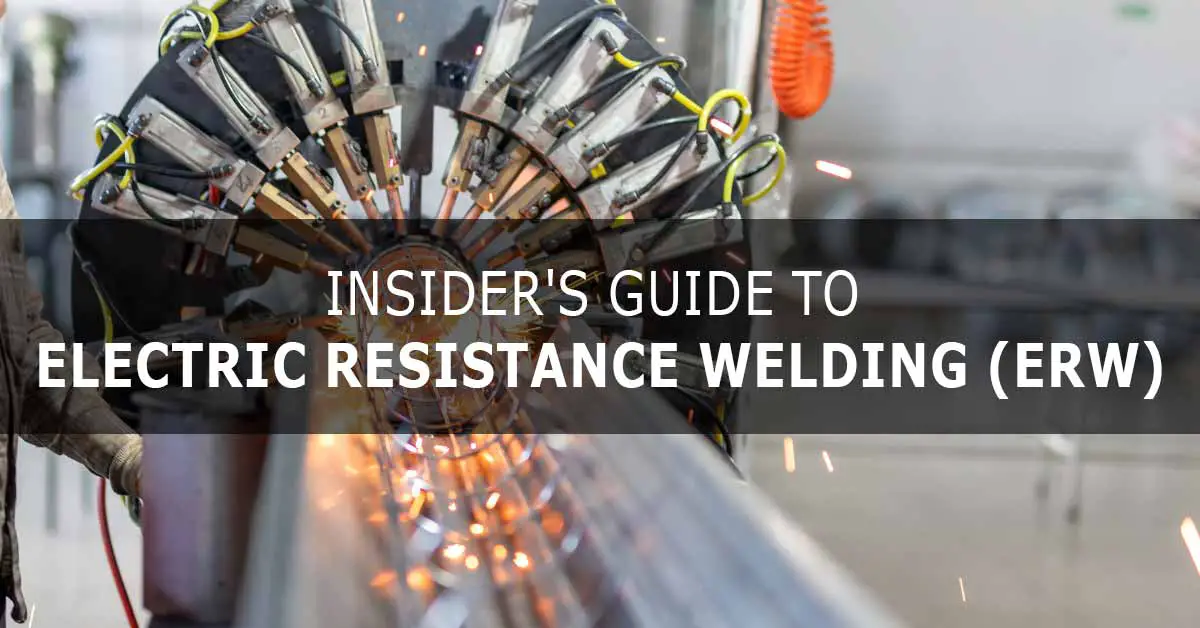
Electric resistance welding (ERW) or resistance welding is the welding process that joins metal parts in contact permanently by heating and melting them at the joint utilizing an electric current. The electric resistance welding process stands out among the other welding processes since it does not use flux, arc, or shielding gasses. It is environmentally friendly, economical, and welder-friendly since the welder does not need to worry about fumes or thermal radiation. ERW is widely used in the manufacture of steel pipes and the assembly of automobile bodies.
What is the principle of resistance welding, and how is it done?
If you connect a piece of metal to an electric source and put it on the switch, electric current flows through the metal piece due to the voltage. The metal piece offers electrical resistance to the flow of current through it, and due to this, the metal becomes hot. A well-known example of this is the heating element we use in domestic ovens or industrial ovens, and all of you probably have seen this. Resistance welding uses the heat generated due to the electric resistance to produce the weld, and suitable weld pressure is applied to make the bond perfect.
When you overlap two thin metal parts and pass current through them, the heat generated at the point of overlapping (due to the electrical resistance for the current flow) is sufficient to fuse the two metal parts. The fusion of the two metal parts can be made better by using a force on the location. This is the principle of resistance welding, and since the resistance of the metal is used for heat generation, the name ‘resistance welding’.

During the resistance welding process, the two metal workpieces are held between the copper electrodes. The application of weld current and pressure are through the water-cooled electrodes. The surfaces of the metals to be welded should be flat, smooth, and free from contaminations and oxides.
In the good old days, two metals were joined by heating the metals and then applying the pressure to join them; this welding was called forge welding. Resistance welding does a similar weld using electric current. Resistance welding is an ideal process for the mass production of parts in the automobile industry.
The heat generated in resistance welding can be explained using Joule’s Law H=I2RT, where H is the heat generated (joules), I2 is current squared, R is the resistance (ohms) in the electrical circuit, and T is the time duration of current flow. When using this equation for resistance welding, a constant K is added on the right-hand side to account for the heat loss to the surroundings.
So, the equation becomes H=K I2RT
This equation shows that the heat generated in resistance welding is proportional to the current squared, resistance, and time. The value of the constant K depends on the metals to be welded, their thicknesses, electrodes used, and resistance.
There are formulae to verify the weldability of metals, and normally such formulae consider the resistance and melting temperature of the metal (to be welded) to calculate the weldability factor. According to one such formula, the weldability of mild steel is more than 10. The weldability value for aluminum is “between 1 to 2”, and it is considered a good factor. The weldability value of copper and some brasses is low, and these metals are difficult to weld by resistance welding.
Resistance welding process
The sequence of events that takes place in a resistance welding process can be described in the following steps.

Squeeze time – Squeeze time is the time needed for the electrodes to align and secure the workpieces together and establish the electrical contact.
Resistance weld time – Weld time is the duration of the current flow through the workpiece until the workpiece’s weld area is heated to the required temperature (melting temperature).
Hold time – The hold time is the duration for which the workpieces are held together under pressure, without the flow of current, to allow the workpieces to get forge-welded.
The off-time – The off-time starts after the pressure of the electrodes is taken off from the workpiece, and the machine utilizes it for readying the workpiece for resistance welding at the new location. The off-time is to be specified when resistance welding is to be done at multiple designated spots.
The heat due to the electrical resistance (resistive heat) happens between the two metal workpieces. The current flows through the electrodes and the metal workpieces and initiates the formation of the weld nugget. Once the welding current is turned off, the weld cools down, and the weld nugget becomes solid and joins the two metal workpieces together. The water-cooled electrodes help in cooling the weld.
Different types of welding bonds in resistance welding are:
- Solid-state.
- Fusion.
- Reflow braze.
1. Solid-state bond
A solid-state bond (also known as a thermo-compression bond) is used to join dissimilar metals with dissimilar grain structures. Resistance welding of tungsten with molybdenum using a short heating time and high welding energy and force is an example of solid-state bond welding. The melting of the metal is low, grain growth is low, and the joining happens in the solid state. The solid-state bond welding has good shear and tensile strength, but the peel strength is low.
2. Fusion bond
Resistance welding with fusion bond is used for welding similar and dissimilar metals that have similar grain structures. The welding point of the two metal workpieces is heated to transform into a liquid state (by electric current), and the welding happens due to the pressure and cooling imparted by the electrodes. A nugget (weld joint) is formed between the two metals, and the nugget is an alloy of the two welded metals with large grain growth. Depending on the metals being welded, the electric energy is applied for a short or long duration to form fusion bonds. Resistance welded metals with fusion bonds have good peel, shear, and tensile strengths.
3. Reflow braze bond
Reflow braze bond is a process of joining two dissimilar metals or two metals of different thicknesses using a third metal (called brazing material) whose melting point is lower than the metals to be joined. This process needs low electrical energy for a long duration. The brazing metal melts and joins the two metals. The brazing metal should be compatible with the metals being joined together. The joints produced by this process have good tensile strength but low shear and peel strength.
Resistance welding parameters
The different parameters that influence resistance welding are:
- Weld current.
- Weld time.
- Weld pressure.
- Contact resistance.
- Properties of metals to be welded.
- The geometry of the electrodes and metal workpieces.
- Characteristics of the welding machine.
1. Weld current
The weld current is an essential factor in resistance welding, and the heat generation depends on the current. The amount of heat generated and the size of the weld nugget increases quickly by increasing the current; however, increasing the current beyond the limit may result in the hot metal coming out.
2. Weld time
The heat generated at the weld joint is directly proportional to the welding time. Considering the heat loss to the surroundings, a minimum weld current and weld time are required to create a good weld joint. A good weld cannot be achieved by keeping the current low and increasing the weld time. Similarly, by increasing the weld current drastically, welding time cannot be brought down. Both the current and the weld time should be optimum for a good weld.
3. Weld pressure
The pressure applied by the electrodes on the metal workpieces affects the contact resistance at the interfaces since the pressure applied on the metal workpieces brings them in close metal contact and enables the passage of current. A low welding pressure will lead to high resistance at the contact area and fast heat generation. On the other hand, high pressure will result in low resistance at the contact area and slow heat generation.
4. Contact resistance
The contact resistance is the electrical resistance at the weld interface (between the two metal workpieces) and is an important parameter that influences resistance welding. The contact resistance is usually affected by the surface finish, and the cleanliness of the metal workpieces and rougher surfaces have higher electrical resistance. Two factors can vary the contact resistance, and the metal considered here is mild steel. The contact resistance decreases with the increase in temperature and the increase in weld pressure.
Like every metal, the metal workpieces in resistance welding have surfaces with micro irregularities, and this creates a gap at the interface and hence higher contact resistance. When the weld pressure is applied on the metal workpieces, the surfaces come into close physical contact and results in reduced contact resistance.
5. Properties of metals
The physical properties of each metal differ from each other, and these properties may change with temperature, and all this can have a bearing on its weldability with resistance welding. Metals like copper and silver have low electrical resistance and high thermal conductivity. The major part of these metals’ heat generated (during resistance welding) may have been lost to the surroundings. This makes copper and silver difficult to weld by resistance welding. Also, during resistance welding of dissimilar metals, more heat is generated in the metal with higher resistance. All these factors are to be considered when designing parts with resistance welding. The hardness of the metals can influence the contact resistance, and they may need higher weld pressure compared to soft metals.
6. The geometry of the electrodes and metal workpieces
The geometry (shape) of the electrodes and metal workpieces play a role and influence the result of resistance welding. The geometry or shape of the electrodes has a bearing on the density of current and the size of the resulting weld nugget. The geometry of the workpiece becomes essential when designing for projection welding, especially if the metals are dissimilar. In dissimilar metals, it is preferred to have the projection on the metal with lower electrical resistance.
7. Characteristics of the welding machine
The characteristics of the machine, electrical and mechanical, have an essential role in the results of resistance welding.
Quality of resistance welded parts
Like other conventional welding processes, resistance welding has problems with oxide entrapment, hot cracking, and porosity. The standard method of testing a resistance welding quality is the peel test. An alternative to the peel test is the controlled tensile test. However, this is difficult to conduct and needs calibrated instruments.
Metal weldability using resistance welding
The weldability of metals is influenced by three factors, viz. electrical resistance, thermal conductivity, and melting temperature. Metals having high electrical resistance, low thermal conductivity, and a comparatively low melting temperature can be resistance welded easily. Most of the ferrous metals come in this category. Metals that have low electrical resistance but superior thermal conductivity can pose problems for resistance welding. Light metals like aluminum and magnesium fit this group. The precious metals (gold, silver, platinum, and palladium) with their very high thermal conductivity form the third group. The fourth group consists of refractory metals with exceptionally high melting points, and these are the ones most difficult to resistance weld.
Equipment used for resistance welding
The resistance welding machines look very compact from the outside. However, it has many complex controls and circuits built inside for its efficient working. The significant parts of a resistance welding machine are:
- Power source.
- Transformer.
- Electrodes.
- Cooling system for electrodes.
- A mechanism to apply pressure on the metal workpieces.
- Electrical and mechanical devices for the movement of the electrodes, current cycle, etc.

1. Power source
The typical power source used is single-phase alternating current (AC); however, 3 phase AC current is also used.
2. Transformer
The requirement of resistance welding is low voltage and very high current. The current required may be in the order of 10,000 amperes or more, and the duration will be in milliseconds. The maximum current available in the residential power supply is 20 amperes and in industrial supply is 200 amperes. The device used in resistance welding to get such a high current value is the transformer. We usually think that transformers are used to step up or step down voltages, but transformers can also transform the current. The electrical circuit that has the welding transformer may include the current regulator also.
3. Electrodes
The electrodes in resistance welding have two functions:
- Conducting the electric current to the metal workpieces.
- Apply the required weld pressure.
Copper is the normal choice as the electrode metal for its high electrical conductivity, and for some applications, copper electrodes with tungsten or other metal inserts are used. The shape of the electrode can be dome, pointed, truncated cone, or custom-made. The shape can even be in the form of a disc or roller (like the one used for resistance seam welding).
Metals with high conductivity like copper are used to resist welding of metals with high electrical resistance such as nickel, stainless steel, etc. Metals with high electrical resistance like molybdenum are used for resistance welding of metals with high thermal conductivity such as gold, copper, etc.
Electrode degradation and tip dressing – The electrodes used in resistance welding may lose their shape and metallurgical properties (near the tip) due to the continuous temperature and pressure it is exposed to. This problem can be handled in two ways:
- Provide the margin for the loss of current and compensate it by modifying the machine’s working parameters.
- Take out the electrodes from the machine and restore their original shape by mechanical machining.
4. Cooling system for electrodes
Extreme heat is generated at the point of welding, and to keep the electrodes in good shape and working condition, electrodes are continuously cooled by water. The cooling of the electrode also helps the cooling of the weld.
5. Mechanism to apply pressure on the metal workpieces
A certain pressure is to be applied on the metal workpieces to complete the welding, and this pressure is applied through the electrodes. The amount of pressure depends on the type of metal workpieces and their thickness and can vary from a few kilograms for thin sheets to a ton or more for heavy metal workpieces.
The applied pressure can be mechanical (using leverage and spring), pneumatic, or hydraulic. In a simple, manually operated machine, the mechanical pressure can be applied using a foot pedal connected to a spring-loaded rocker arm. In a fully automated or semi-automated machine, the function of pressure and its duration is taken care of by automatic systems.
6. Electrical and mechanical devices for the movement of the electrodes, current cycle, etc.
There are different functions in a resistance welding machine that needs to be coordinated and controlled. Mechanical functions like loading and unloading the metal workpiece, movement of the electrodes, pressure, cooling water, etc. Then there are things like the density of current required, duration of the current, pressure on the electrodes, etc. The modern resistance welding machine uses digital microprocessor-based controls, and the complete sequence of the resistance welding is automated.
Types of resistance welding machines
1. Semiautomatic and fully automatic resistance welding machines
Resistance welding machines can be completely mechanized (fully automatic) or semiautomatic type. In the semiautomatic type, the welder has to position the work manually between the electrodes and then press a switch to start the weld, and the machine does the welding as programmed.
In a completely mechanized machine, metal workpieces are fed into the machine automatically, welded as per the program, and ejected without the need for the operator’s assistance. This type of resistance welding machine is designed and produced for different applications in automobile, industrial, and aerospace applications. Such machines are known for their high level of production and repeatability.
2. Spot resistance welding machines
There are different types of resistant spot welding machines such as rocker arm, press type, multiple weld type, portable type, and robotic type. The electrode arms are made in such a way to permit a spot to weld at a substantial space from the edge of the metal sheet. The electrodes are typically made of copper alloy, and they can apply sufficient pressure or squeeze during the welding.

- Rocker arm type machine – Rocker arm type of machine basically has a rocker arm that transmits the electrode pressure and, in most cases, the weld current. These machines are adaptable for spot welding of most weld-able metals. Since the movement of the arm is of rocking (travel path is an arc), the top electrode is to be positioned accordingly. Because of the rocking motion, this machine is not suitable for projection welding.
- Press type – In the press type resistance welding machine, the welding head travels in a straight line path on guideways. The machine is classified based on the type of force applied, and the type of force can be pneumatic, hydraulic, or manual (manual is used for small units). The press-type resistance welding machine can be designed for spot welding or projection welding, or both.
- Portable type – A normal portable resistance spot welding machine comprises of four basic units: portable welding tool or head, welding transformer (and a rectifier in some versions), electrical contactor, sequence timer, and, set of cables for power connection and hoses for cooling water.The construction of a welding head includes a frame, pneumatic or hydraulic system for pressure, hand grips, and a starting switch. The design and construction of the welding head will be specific and tailor-made for the unit to be welded.
- Multiple spot welding machines – Multiple spot welding machines are normally made specific to a part or assembly. The application will be in the mass production industry like the automobile industry or household items industry. This machine produces two or more spot welds simultaneously.
- Robotic spot welding machine – One of the ways of automating resistance welding is to use robots to carry out the welding, and the robotic hands have to carry the resistance welding head to the place of welding to do this. To make this possible and maneuverable, the resistance welding head should be designed light and compact. To make the resistance welding head compact and light, the welding transformer is separated from the welding head, and they are connected through cables. The separation of the welding transformer from the resistance welding head may lead to power losses.The robot places the welding head at the welding location, the electrodes clamp the metals, the current is passed, and the weld is completed. The robot moves the welding head to the following welding location, and the welding action is repeated. The travel between the weld locations can be made fastest by the shortest route. The robotic resistance welding suits the spot welding process.
Related Article: What You Need To Know About The Types Of Electric Resistance Welding
Applications of resistance welding
- Most of the metals like aluminum, magnesium, nickel, precious metals, mild steel, low alloy steel, low carbon steel, and stainless steel can be welded with resistance welding; however, the methods, type of electrodes, and machine parameters may differ.
- Resistance welding can be used for the welding of metals as thin as 0.15 mm thickness to metals of 18 mm thickness or more. The speed of the welding depends on the machine’s capability.
- Resistance welding can weld dissimilar metals and metals of different thicknesses.
- Electrical resistance welding is widely used in the automobile industry and for the manufacturing of pipes.
- Widely used in the automotive industry for the joining of body parts and large sheet metal parts.
- Used for the manufacture of metal wire shop trollies and metal wire baskets.
Electric resistance welding advantages and disadvantages (limitations)
Advantages
- An extremely high rate of production makes resistance welding ideal for mass production items.
- Resistance welding is very quick in its operation.
- The resistance welding process can be completely automated.
- Less skilled welders can operate the resistance welding machine.
- Welding of dissimilar metals and metals of different thicknesses is possible.
- Resistance welding has a high level of reliability, consistency, and repeatability.
- Environmental and human friendly since there are no toxic gasses and thermal radiations.
- The resistance welding process can be mechanized and automated.
- This process does not need filler metal, flux, or shielding gasses; hence the process is economical.
- The resistance welding does not have fumes and thermal radiations and hence environmentally friendly and friendlier to the welder.
- A simple process that a low-skilled welder can manage.
Disadvantages (limitations)
- The equipment is highly expensive and complex.
- Need highly skilled personnel for setting and maintaining the machine.
- The maximum thickness of the metal is a limitation.
- This process is less suitable for highly conductive metals like copper.
- The energy cost is high.
- Machines cannot be taken out for fieldwork.
- Limited to very few types of weld joints (largely lap joints).
- Certain metals need particular surface preparations before resistance welding.
Electric resistance welding safety considerations
- The resistance welding process uses high current, and the machine has many electrical circuits for the operation of the machine.
- The welding operator has to wear shoes and hand gloves recommended for work on such machines.
- The welding operator should be careful about the dampness on the floor, and it is better to have a wooden platform for the safe standing of the operator.
- The electrode is under pressure and closes and opens very fast during the operation. The welding operator should take care of his hand.
- The welding operator must wear the proper dress, and loose or hanging clothes are not allowed.
- The welding operator must be thorough with the sequence of operations before pressing the button.
Conclusion
Resistance welding is highly adaptable for mass production; it is environmentally friendly, economical, and green process. All these make resistance welding the technology of the future. However, there are some limitations, which hopefully will be minimized or eliminated in the coming days to make this process more affordable.
Interesting Article: Everything You Need To Know About Cold Welding.
References