Metal forming processes are broadly divided into bulk metal forming and Sheet metal forming processes.
Forging (open die forging, impression die forging, press forging), swaging, radial forging, roll forging, extrusion, ‘wire, rod, and tube’ drawing, and rolling are the bulk metal forming processes.
In this article, we will explore all bulk metal forming processes one-by-one.
Read: An Overview Of Metal Forming Process.
Read: The Last Guide To Sheet Metal Forming You Will Ever Need.
Bulk metal forming processes
1. Forging
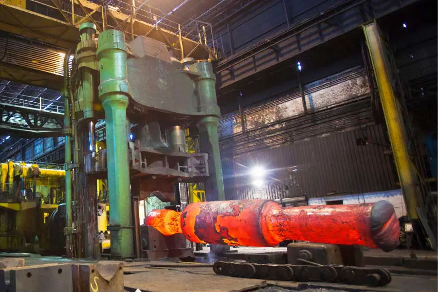
Forging is a process where you will deform the metal to the desired shape by applying compressive forces either manually or using power hammers, presses, or specially designed forging machines.
You can carry out the forging process in a cold, warm, or hot state, on a forging hammer (impact load) or forging press (gradual load). Also, you can do the forging using an open die or a closed die (with or without flashes). Forging is used to produce discrete parts. Connecting rods, crane hooks, gear blanks, rivets, bolts, shafts, crankshafts are some of the typical parts produced by the forging process.
Forge-ability is a term used to indicate the capability of a metal to undergo deformation (forging) without cracking. Different forging processes are open-die forging, impression-die forging, press forging, swaging, radial forging, and roll forging.
A. Open die forging
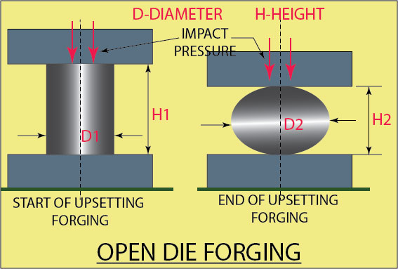
This is the simplest form of the forging process and is very flexible. Here, you will be compressing the workpiece (a billet) between two flat die plates (stationary lower die and a moving upper die). The plastic deformation or the flow of the metal happens freely without any restrictions. You can do open die forging in cold, warm, or hot conditions.
You can call open die forging as the upset forging since the diameter of the billet increases and the height decreases during the process. In an ideal condition, the billet of X diameter and H1 height is forged to Y diameter and H2 height (Y is more than X and H2 is less than H1). However, practically it may not happen exactly this way. The material can simply bulge during upsetting, and the exact form depends on the skill of the operator.
Advantages of open die forging
- The process is flexible and straightforward.
- The die and punch are generic in nature.
Disadvantages of open die forging
- Not suitable for mass or large-scale production.
- The process is slow.
- The quality of the forging depends on the skill of the operator.
B. Impression die forging
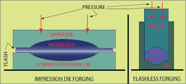
The dies of your impression die forging has cavities in its upper and lower halves, and the workpiece takes the shape of the cavity when it is compressed. The cavities in the die significantly restrict the flow of the metal. Impression die forging is also known as closed die forging since both the upper and lower halves of the die contribute to the shape of the forging. Impression die forging is usually done in a hot state.
You can keep the hot metal workpiece on the cavity of the lower die and compress by one or two blows by the upper die. The hammering or the upper die’s impact action makes the metal flow and fill the cavity completely. The excess metal flows out of the cavity (around the periphery), and this is called flash. After the forging is completed, the flash can be removed using a trimming die.
Many impression die sets have multiple cavities, and the final forging shape is achieved by more than one stage of forging. Flash-less forging is another form of impression die forging, where the flow of deformed metal is restricted within the die, and no flash is produced. You have to calculate and control the amount of workpiece metal to match the volume of the die cavity.
Advantages of impression die forging
- The die is not very costly.
- The process is useful for simple shaped parts.
- The grain structure is favorable when compared to parts produced by casting or bar stock machining.
Disadvantages of impression die forging
- Not capable of close tolerances.
- In most cases, an additional machining operation is required.
Application of impression die forging
- Impression die forging is used to manufacture parts used in the automobile, defence, aerospace, aircraft, and tooling industry.
C. Press forging
The press forging may look similar to impression or closed die forging; however, there is one significant difference. The forming process in a press forging happens due to the gradual squeezing of the metal (unlike the hammering in impression forging) and happens in one stroke of the press. Press forging works by applying a slow and continuous (gradual) pressure, and the amount of time the dies are in contact with the workpiece is much more than impression forging.
One negative point is that the workpiece is in contact with the die for more time and loses its temperature very fast. If the deformation continues at its reduced temperature (hence reduced ductility), cracks may form.
Advantages of press forging
- Parts of press forging have a better finish and dimensional accuracy and are suitable for large-scale production.
- Suitable for steel, aluminum, brass, and many alloys.
- Precision press forged parts can have a net shape or near-net shape dimensions and hence require nil or minimum secondary machining.
Disadvantages of press forging
- Higher tool cost.
- Not suitable for large parts.
- Not suitable for low-scale production.
- Not suitable for complex shapes.
Applications of press forging
- Widely used for parts used in automobile, aerospace, and allied industries.
- Many parts like small crankshafts, connecting rods, pneumatic fitting bodies, gear blanks, etc., are made by press forging.
2. Swaging
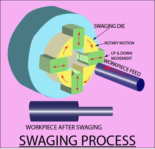
Swaging is a process where you can reduce a rod or tube’s diameter by forcing it through a confining die. The radial blows provided by a set of reciprocating dies cause the inward flow of the metal and take the shape of the die cavity.
The workpiece is held in the machine and remains stationary, and the rotating die moves on to the workpiece. The dies may strike the workpiece as high as 15 to 20 strokes per second. When you are swaging a pipe, you can control the pipe thickness and the internal diameter using an internal mandrel. Swaging of small diameter tubes is done by using a thin rod as a mandrel. The maximum diameter of the workpiece that can be swaged is 150 mm, and the minimum diameter is 0.5 mm. Use a lubricant for ease of operation and a better surface finish and die life.
The production rate depends on the individual machine, workpiece feeding system, and workpiece complexity and can be up to 30 components per minute. Swaged components have improved mechanical properties and a high level of tolerance (±0.05 mm to ±0.5). The swaging operation makes noise, and the noise can be controlled by suitable foundation/mounting and an enclosure.
Advantages of Swaging
- Suitable for large-scale production.
- A low-skill operator can do swaging.
- Good surface finish and strength.
- A high level of accuracy is possible.
- Most metals such as low carbon steel, aluminum, stainless steel, brass, etc., can be swaged.
Limitations of Swaging
- Noisy operation.
- Limitations of maximum diameter/size.
Application of Swaging
- Some of the typical swaged items are pipe ends, screwdriver blades, soldering iron tips, etc.
- Hot swaging is used for large reductions, steep or long tapers, and also for metals like tungsten and molybdenum (they have low ductility at room temperature).
3. Radial forging
Radial forging is similar to the swaging operation, with the exception in radial forging that the dies do not rotate; instead, the work rotates as it moves through the hammering dies.
4. Roll forging
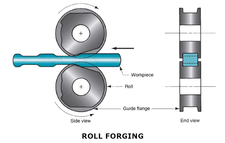
Roll forging is a forming process that you can use to reduce the cross-section of cylindrical or other cross-section workpieces by passing it through a set of rollers with matching groves. The rollers move in opposite directions, and the groves on the roller are made considering the final part’s desired shape. Roll forging uses the technique of rolling and forging.
Depending on the workpiece (amount of deformation), the rollers can rotate wholly or partially. Roll forging can be used for workpieces with one or more step diameters.
Advantages of roll forging
- Suitable for large-scale production and component cost is low compared to conventional processes.
- There is no scrap generation.
- The part has better strength compared to the machined part.
Limitations of roll forging
- Not suitable for low production quantity.
- High initial investment.
5. Extrusion
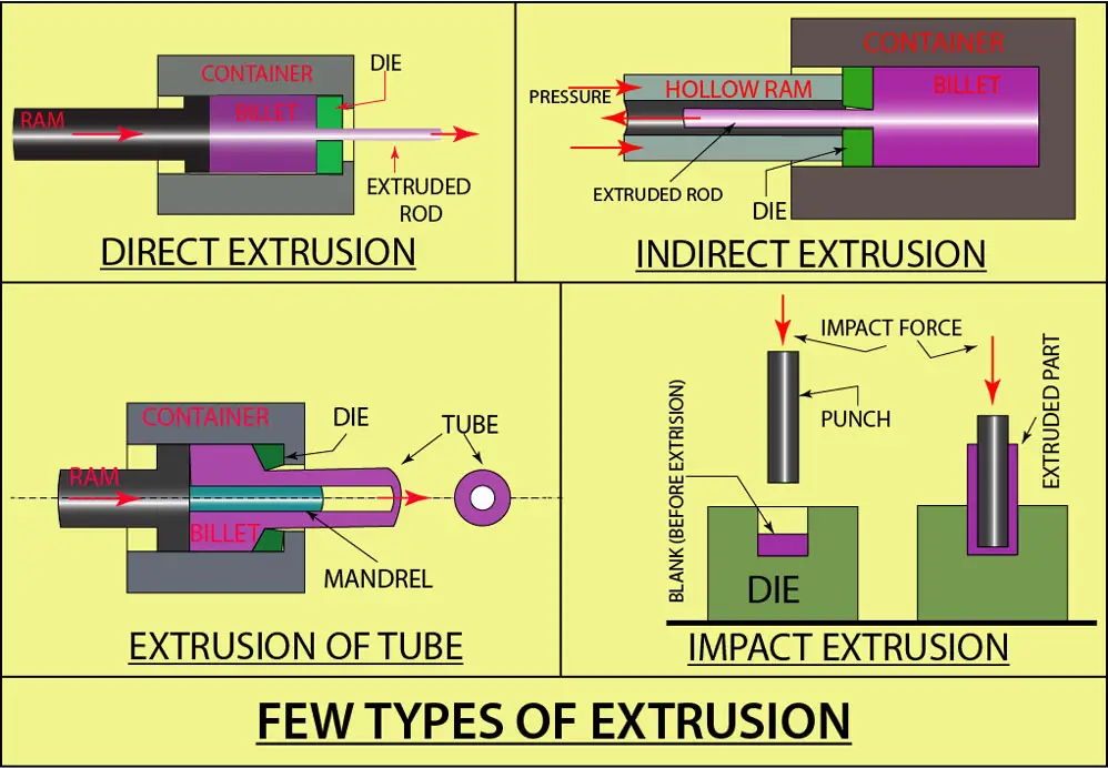
Extrusion is a process where you are forcing the metal billet to flow through a die hole to produce a rod of the desired size and cross-section. When you squeeze the toothpaste by compressing the tube with your fingers, you are actually doing an extrusion process, and the cross-section size of the toothpaste coming out depends on the size of the exit hole.
There are two types of extrusion forward or direct extrusion and backward or indirect extrusion.
A. The direct extrusion
A metal billet is loaded into the container, which has a die hole. The billet is compressed with the ram, forcing the billet metal to flow through the die hole. Some portion of the billet metal that cannot be extruded is left in the end, it is called a butt, and the same is cut off from the extruded product.
In cold direct extrusion, a substantial amount of friction occurs between the surface of the container wall and the billet surface, and higher ram force is required to overcome the friction. In hot extrusion, friction is heightened due to the presence of an oxide layer on the billet surface, which can cause defects in the extruded bar. This issue is resolved by placing a dummy block between the billet and the ram. The diameter of the dummy block is less than the billet diameter, and in the end, a thin layer of the billet containing the oxide layer is left sticking to the dummy block, and the final product is free of oxides.
You can make hollow extrusions (tubes) by direct extrusion process and using a mandrel. When you compress the billet with the ram, the material flow happens through the gap between the die hole and the mandrel. The billet, in this case, will have a central hole for the mandrel.
B. Indirect extrusion
In this type, the ram is hollow, and the die is mounted on the ram. When the ram compresses the billet metal, the metal flows through the die and passes through the ram. Since there is no relative movement between the billet and the container, friction is less, and hence the ram force is lower than direct extrusion. However, since the ram is hollow, there is a limitation of the force applied.
Another extrusion processes are impact extrusion, where an impact pressure is used (instead of continuous pressure). Impact extrusion can be done as forward extrusion, and backward extrusion, or a combination of both.
Advantages of the indirect extrusion
- Different cross-sections can be extruded, specifically in hot extrusion.
- Grain structure and strength are improved in cold and warm extrusion.
- Close tolerances and a good surface finish are possible in cold extrusion.
- The process is flexible.
Disadvantages of indirect extrusion
- A high initial setup cost.
6. Wire, rod, and tube drawing
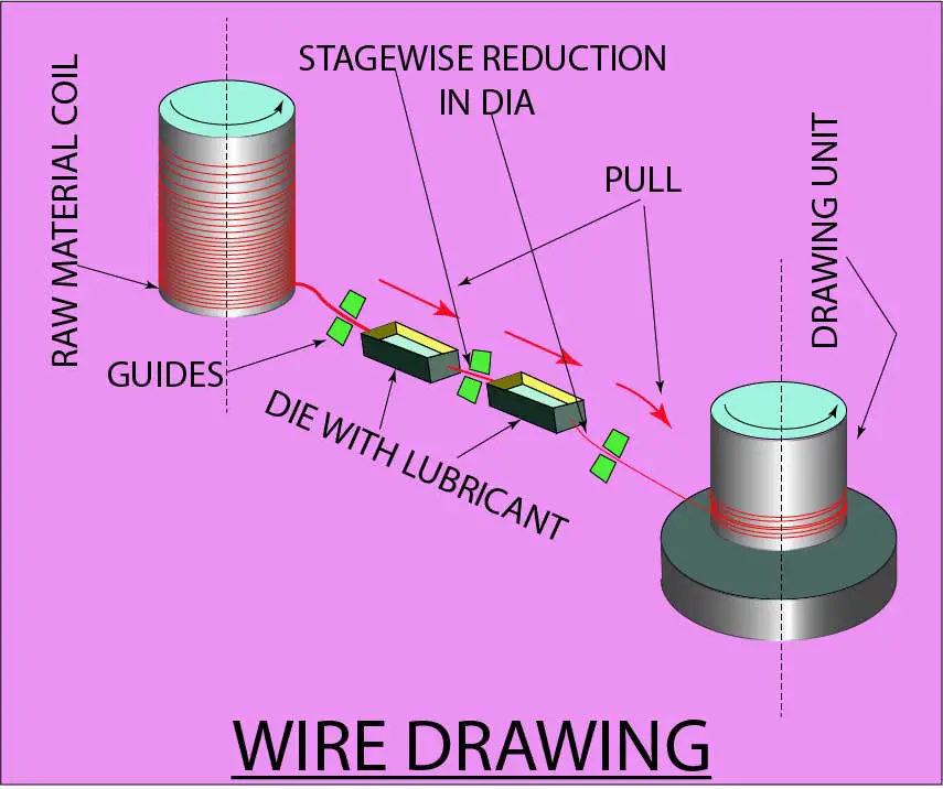
In the drawing process, a wire or a rod is pulled through a die hole to reduce its cross-section area. The primary difference between a wire drawing and a rod drawing is the size of the work. Rod drawing is used for a larger size of work, while wire drawing can be used for drawing of wires as less than 0.03 mm.
Rod drawing usually is completed in a single-stage operation by pulling the work stock through the die opening. The rod on the input side of the die is straight (not in coil form) and of a particular length; hence there will be a break after the drawing of one rod is completed.
The wire drawing process is the same as rod drawing, except that the diameter involved is small, and the wire can be continuously coiled after drawing. Unlike rod drawing, wire drawing cannot be done in one stage. The wire is usually drawn on a drawbench where a series of dies is placed for drawing (every die is held in a die block which is cooled by water). The wire passes through each die, undergoing a small amount of reduction, and the final size is achieved when the wire exit the last die. The reduction of wire diameter in each die is small, which is necessary to avoid excessive strain in the wire.
The angles of the wire drawing die facilitate the optimal pulling force needed to draw the wire. The wire drawing dies are typically made from tool steels and carbides, and for fine wires, diamond dies are used.
Lubrication of the work/die is essential and improves die life, reduces draw force & temperature, and improves surface finish.
A large coil of hot-rolled material (approximate diameter 10 mm) is taken and is prepared for wire drawing in the following steps:
- The metal coil is cleaned by acid pickling, followed by rinsing and drying.
- The traces of acid retained on the coil are neutralized by immersing the coil in a lime bath.
- The metal coil is given a thin coat of lubricant to protect it against rusting.
- Reduction in the cross-sectional area per pass can range from negligible (near zero) to 45% and depends on various factors such as type of metal, its size, metallurgical condition of the work material, the desired final size and mechanical properties, design of the die, and efficiency of the lubrication. Any attempt of reduction of more than 45% may result in the deterioration of the surface finish. There can be a sizing pass (negligible reduction in cross-section) to improve dimensional accuracy and surface finish.
- To start the wire drawing process, you have to reduce the cross-section of one end of the coil, feed it into the first wire drawing die, and put it in the gripper on the other end.
Tube drawing
The tube drawing process is similar to the rod or wire drawing process, except that you usually need a mandrel of the required diameter to form the internal diameter of the tube. The mandrel can be fixed type or floating type. There is a length restriction for pipe drawing when you use a fixed type mandrel; however, there is no length restriction for floating type mandrel.
The diameter and wall thickness of a seamless tube can be reduced using the tube drawing process. Tubes as large as 300 mm (30 CM) can be drawn.
A draw bench is used for single-length drawing of tube or rod, the diameter can be greater than 20 mm and length as much as 30 meters. Very long rods of less than 13 mm diameter and wires of smaller cross-sections (length can be in kilometers) is normally drawn by a rotating drum and the tension provided by the rotating drum is sufficient to draw the wire through multiple dies.
Advantages of tube drawing
- Suitable for large-scale production and cost-effective.
- Can be used for most metals.
Limitations of tube drawing
- High initial cost.
- Limitations in the reduction of cross-section per stage.
Application of tube drawing
- Used for the manufacture of wires, flats, rods of different cross-sections, tubes, etc.
7. Rolling
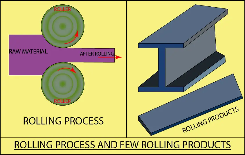
Rolling is a metal forming process where you can use the compressive force exerted by the two rollers (moving in opposing directions) to reduce the thickness of the workpiece or change the workpiece’s shape. Rolling used for reducing thickness is called ‘flat rolling‘, and that used to change the shape (I-beam, rails, channels, etc.) is called ‘shape rolling‘.
The work material used in rolling are:
- Bloom – A bloom has a square cross-section of 150 mm×150 mm, or more. Blooms are used to roll structural shapes like I-beam, rails, etc.
- Slab – A slab is rolled from an ingot or bloom, and the cross-section is rectangular, 250 mm width or more× 40 mm thickness or more. Slabs are rolled into plates, sheets, and flats. These sheets can be further cold-rolled into thin sheets.
- Billet – A billet is rolled from bloom and has a square cross-section of 40 mm×40 mm, or more. Billets are rolled into bars and rods.
Advantages of rolling
- The rolling process is suitable for large scale production.
- One set of rollers can be used for flat products of different thicknesses.
- The thickness of the product is relatively uniform.
- Continuous production of different shape products is possible.
Disadvantages of rolling
- The initial cost of the equipment is very high.
- Not suitable for low-scale production.
- The surface finish is not finished, and secondary operation is required.
Application of rolling
- Rods, bars, plates, and sheets are used in almost every industry.
- I-beams, channels, etc., are used in fabrication works.
- Rails are very crucial for the movement of passengers and goods.
Conclusion
You can define metal forming as a process that makes use of its ability to flow plastically under force (pressure) to transform the metal to the required geometrical shape.
Metal forming is achieved by the permanent deformation of the metal to a desired and useful shape. However, the amount of pressure applied should be sufficient for the metal to the yield-point for permanent deformation. Any increase of pressure beyond a limit leads to cracks/material failure.
The metal forming can be done in three conditions cold, warm, and hot. Cold forming indicates the forming of metal at its room temperature, and warm and hot forming indicates forming of metal at its elevated temperature.
References:


