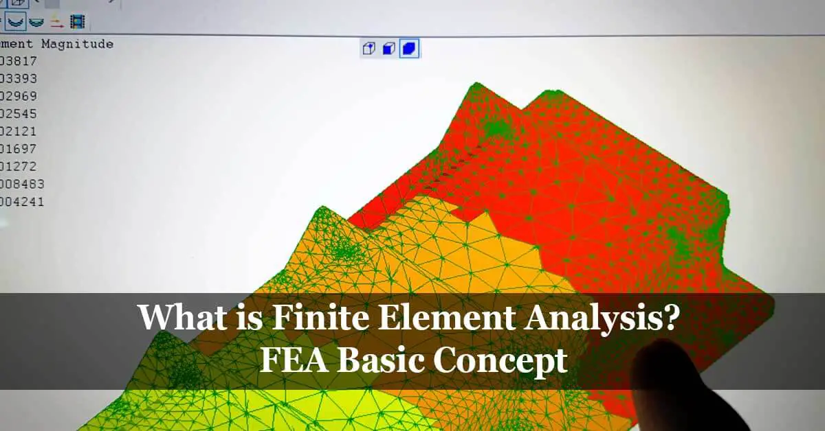
Finite element analysis or FEA is the analysis of product reaction towards real-world forces, vibration, heat, fluid flow, and other varied physical effects by using computerized systems. Finite element analysis shows the product’s design reliability and its ability to withstand the various external physical effects.
Are you in the mechanical engineering field? Then you must have learned about finite element analysis. If you simulate a physical phenomenon with mathematical methods and a numerical system, it is termed a finite element method or technique.
Several scientific disciplines, especially mechanical engineering, rely on this method for the solution of some issues. Simulation software is created on the fundamental formulas of finite element analysis. Finite element analysis has a lot of uses and applications. Significantly, engineering professionals reduce the number of physical prototypes by applying simulation analysis; they may process remote experiments to optimize their models.
Advanced knowledge of mathematics is required to get an insight into the physical nature of happenings around us. These phenomena include fluid dynamics, wave, and thermal studies. We may use partial differential equations to analyze such things, but there may be some complicated things where you need to use exceptionally variable equations. It is a mathematical method used for such analysis.
Finite Element Analysis evolution
During the 16th century, the reputable mathematician Euler used this analysis. Even before Euler, a rigid form of FEA type is associated with the experiments conducted by Schellbach in 1851.
Engineers use finite element analysis to eliminate the mechanical issues in civil engineering and the space industry, and this method was intended to use as a mathematical approach. Still, now it has widespread applications in physics and engineering. It was a theory until 1950, but it became a part of real-world usage, and engineering experts started applying it in different situations. Now the principles of finite element analysis are involved in various fields, including civil engineering, computational fluid dynamics, prototype development, aerospace studies, etc.
How FEA works? Finite Element Analysis process description
Engineers integrate the FEA algorithms into a simulation tool such as Autodesk Inventor or other suites of software. Then combine these programs with CAD software. The process makes it easy for engineers to run the advanced structural analysis to test their models, prototypes, and designs.
For running a finite element analysis, the engineers generate a mesh. It contains millions of tiny components and develops an overall shape. In this way, they may encode the 3D shapes into a mathematical structure to test and analyze. You may change the density and concentration of mesh based on the simulation type you need.
Calculations
First, the engineers run the finite element analysis for individual elements or components of mesh. Then they juxtapose it to get cumulative results of the structure and reach a conclusion. There may be some interpolation required to take place between different elements. These estimates remain within certain limits according to the need of the situation.
Nodal points
Nodal points are the points of the mesh where the data is calculated in mathematical terms. It is then reshaped around the boundaries or the area where change occurs in the design of a shape or physical object. You may use FEA for thermal analysis that takes place within a body or figure.
Example
Suppose you have a piece of information about the temperature of one part of a body or object. You will be interested in determining the temperature of the other end of the same thing. Does it depend on time? You may benefit from the finite element analysis approximation process. You may use different modes to reach an accurate result. These approximations include:
- Square approximation
- Discrete approximation
- Polynomial approximation
You may use any technique to reach an accurate outcome in the complex phenomenon.
Different Types of Finite Element Method
The application of finite element analysis provides accurate results to a wide range of problems. Here are some different types of finite element method, such as:
- Extended finite element analysis or XFEM
- Generalized finite element or GFEM
- Mixed finite element analysis
- Hp-finite element
- Discontinuous finite element analysis
- Applied Element Method or AEM
The finite element analysis has application in different branches of engineering and science. It has now evolved into different types and methods and may be used in variable complexity levels.
Applications of Finite Element Analysis
Finite element analysis is used in different engineering fields for research and modeling purpose. With it, engineers can get more efficient and precise modeling features of different complex systems. Here is an overview of some applications of finite element analysis.
Mechanical engineering: FEA method is used in the mechanical engineering field for thermal analysis, stress analysis, and automotive modeling in solids and fluids. We may also use it for manufacturing process simulation.
Geotechnical engineering: FEA may be applied to conduct stress analysis, slope stability evaluation, and soil structure analysis. We may use it for the space of fluids in soils and rocks. It may be used for dams, tunnels, and boreholes analysis.
Aerospace: Aerospace engineers use this type of analysis for structural analysis to get insight into natural frequencies and mode shapes. This method is also vital for response analysis and aerodynamics.
Nuclear engineering: The finite element method is applied to analyze reactor containment’s steady and dynamic features. Nuclear researchers use it for viscoelasticity analysis of reactor components and other nuclear-related structures.
Other applications: The finite analysis is also used for electrical and electronics analysis and metallurgical and chemical engineering fields. Meteorology and biotechnology also benefit from this method.

FEA application on structure analysis explanation
We may conduct Finite element analysis in different sectors, including structural and civil engineering, to the approximate physical structure. It provides regular analytical solutions for complex issues. We may numerically analyze such phenomenon with precision and accuracy.
Take the example of a concrete beam that has support on both sides. It carries the concentrated load on its central point. You may define the deflection on center span mathematically only with finite element analysis. Besides, you may calculate that initial and boundary conditions. If you move the beam for a practical application to use in a bridge, it may be complicated to calculate the forces in a simple mathematics way.
Suppose you are building a residential house or a building like Burj Khalifa. In that case, you need to assess the structural behavior and integrity of your space for the safety of its inhabitants and occupants. If your structure is subjected to loads, you may determine its behavior through structural analysis. The loads may be the result of gravity, wind, or a natural disaster like earthquakes. It would help if you analyzed its strength to stand with these natural extremities. We may do so using some fundamental mathematical formulas. In this way, you may understand the behavior of a building, bridge, dam, or their foundations.
In a normal situation, buildings like Burj Khalifa undergo an oscillation process at the highest point. If you are living on the top floor, you may feel such a motion. There are some reasons to control such oscillation, and these motions can be restricted by using dampers; for example, the famous tuned mass damper in Taipei 101 is an example of such dampers.
You may use some standard formula for a solution to this behavior of structural. Some solutions for determining it as the moment distribution process, unit load formula, stain energy method, etc.
You may analyze different structures such as beams, supports, and trusses through the methods mentioned above and assess the design’s structure and overall features. You may solve a lot of such problems with the application of FEA; however, you need to go advanced and go through the more in-depth process for non-conventional forms.
The engineers and researchers developed different theories after laboratory experiments to provide solutions to design issues in various structures. The behavior of steel structures facing high wind intensities and earthquakes was the subject of concern for engineers.
The laboratory tests and evaluation was an expensive and scarce process. For this purpose, the researchers developed structural codes. The engineer could get an insight into the acceptable behavior of structures, and they could determine the safety measures for residents. Now there are CAE tools that are easily assessable. With these tools, design process, testing, and modern structures’ safety are now cheaper, faster, and more available. The structural engineering areas where you can apply FEA rules are various and vast in scope.
Modern structural materials
Concrete has been in use as a building material for a more extended period. The research has proved different behaviors like alkali-silica reaction. What is the reason for cracks in concrete structures, and is there a relation between composition and martial to influence these cracks? Is there any solution for this purpose?
The most significant issue in FEA simulation is that you cannot quickly determine the material behaviors. The multiscale modeling can solve this issue; you can use microstructure to evaluate concrete properties.
Sedimentation properties
As water motion is concerned, the coastal area water flow is more predominant than it is in other inland waterways. There are some complications in the generation of water waves and tides in seas. Similarly, oceans currents, storms, and winds are some other complication issues. It is a matter of concern for reassesses, and these factors damage the marine structures.
Studying these water flow problems is complex. Similarly, boundary conditions of reflection and diffraction of wave-current are also a matter of concern for engineers to provide solutions and analyze the phenomenon. With the application of FEA, these issues can adequately be examined.
Catchment regions hydrological models
It is something complicated for coastal areas and catchment areas. Hydrological models have been developed through the application of FEA. We may understand the flow of water in porous lands, and in this way, the groundwater levels can be determined.
Linear static analysis is applied to hydrological projects, such as determining a river water load on dams. We may apply a non-linear analysis to study the conveyance system’s effect, such as the inner cushion surface.
Computational Fluid Dynamics (CFD) explanation and application
While creating a new product, the thing an engineer needs to consider is aerodynamics in its structure. You may not quantify the aerodynamics during the concept phase. An engineer conducts the tests on product prototypes to optimize the models and layout of the product. The computers and scientific laws have made it simple and easy for engineers to conduct the tests. Here the computational fluid dynamics comes to lay its role.
Now you may generate solutions for fluid flows with reliable contacts or without them. In the computational fluid software analysis, you may examine the physical properties of the fluid. These properties include:
- Velocity.
- Pressure.
- Temperature.
- Density.
- Viscosity.
The product developers need to consider these properties simultaneously to virtually create a correct physical phenomenon solution related to fluid flows.
Computational Fluid Dynamics mathematical model
For the analyzation process associated with fluid, a mathematical model is developed. To evaluate the physical case, numerical methods are applied in CFD software for this process. For example, you may apply N-S equations as a model to assess material properties. Through this process, you may get insight into material properties concerning fluid flow and heat transformation. There are some changes in the mathematical model according to the content of the problem, including:
- Heat flow.
- Mass transfer.
- Phase transformation.
- Chemical reactions.
The structure of the process is also a factor in the reliability and accuracy of CFD analysis. If you want to solve such problems through an accurate case, the mathematical model is essential. You may verify it through CFD analysis. You may generate reliable solutions by determining the proper numerical method, and start a sustainable product development process through this type of research. Through CFD, it is possible to reduce the number of physical prototypes.
The mathematical models span the computational fluid dynamics with diversified tools. The other computational methods are also there, such as:
- Numerical methods.
- Computational tools.
- Post-process facilities.
- Mathematical models.
There are some other math-based approaches to model the physical phenomenon. You may integrate it with some other numerical methods. It would be best if you committed to conscious rapprochement for developing CFD software. You may find a lot of licensed tools and software for computational analysis.
Equations that cover CFD analysis
Some governing equations direct the central structure of the thermo-fluids testing process. These equations have a foundation on the conservation law of physical properties.
The three rules of conservation determine the fundamental equations of the Computational analysis method:
- Continuity equation or law regarding the conservation of mass.
- Momentum conservation or the second law of motion.
- Law of conservation of energy or the first law of thermodynamics.
According to these laws, mass, momentum, and energy are constant within bounded conditions.
Computational Fluid Dynamics applications
If you are working on fluids, you will need CFD analysis. It is a fact that cannot be denied, and you need to go through the process of CFD simulation for specifying an accurate mathematical model of the real-world case-study. You may do so through rapprochements and assumptions to get a direction through the solution procedure. In this way, you may examine the model in the computational domain.
The fluid movement on a spherical or cylindrical surface is a repetitive issue and maybe solved through CFD analysis. The same type of phenomenon is virtually found in the flow of clouds in the atmosphere.
Incompressible and compressible fluid flow
You may find an accurate solution through analysis if the compressibility of fluid is no more negligible.
Laminar or turbulent movement
In this type of analysis, the turbulent models are a factor. It would be best to have the extensive computing power for turbulent simulation and come through the complicated numerical models the difficulty of truculence changes with the simulation process change. It would help if you calculated the entire domain where the simulation is going on. The turbulent flow analysis may be demonstrated in a valve as an example or any component under study.
Mass and heat flow
There are different aspects of mass flow simulation, including smoke propagation, inert scalar transport, or gas distributions.
We may use a CFD analysis to solve such types of simulations. The best application of mass and heat flow analysis, for example, is the heat exchanger.
References: