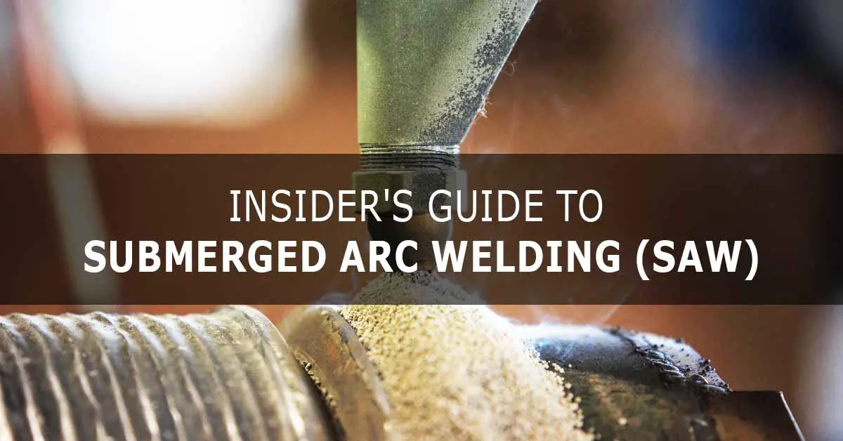
Submerged Arc Welding (SAW) is an arc welding process that forms an electric arc between a continuously fed consumable solid or tubular electrode and the workpiece to be welded. The arc zone and the molten weld are protected from atmospheric by being “submerged” under a blanket of flux. When molten, the flux becomes conductive and provides a current path between the electrode and the workpiece, and generates a protective gas shield and a slag, all of which protect the weld zone.
The submerged arc welding (SAW) process was first patented in 1935. It was developed by Paton Electric Company, Kyiv (now Ukraine), and is known to have been used during the manufacture of the T34 Tank for the Second World War.
What is submerged arc welding, and how it works?
Submerged arc welding (SAW) is a type of arc welding process. It uses the heat generated by an arc struck between the continuously fed bare electrode and the workpiece for melting the surface of the workpiece metal and the wire electrode to create a molten weld pool. The arc is maintained automatically. The melted wire electrode is added to the molten weld pool, forming the weld metal on cooling.
The distinct feature of the submerged arc welding is that it uses a continuous flow of powdered flux (in granular form) to protect the weld pool and reduces the cooling rate of the weld metal. The thick layer of the flux covers the weld pool and shields it from the atmospheric air and contaminations. The flux powder closer to the molten weld pool melts and intermixes with it and helps to purify. The molten flux, on cooling, forms a glass-like slag that floats on the weld metal as a protection cover. The flux and the slag cover the arc completely, and hence the arc is not visible from outside. The quantity of the flux used in SAW is such that the arc is normally not visible to you from outside. The arc is submerged under the flux, hence the name submerged arc welding. Apart from protecting the weld pool, the flux can be used for adding the desired alloying elements to the weld pool. Submerged arc welding is a very useful and versatile welding method. The unused flux (that is not melted) is recovered for recycling.
The submerged arc welding needs a continuous feed of consumable wire electrodes along with a continuous supply of the flux powder. The wire electrode can be a continuous solid or cored wire, or a strip. The pouring of the flux powder on the weld length precedes the welding arc always to keep the arc submerged under a thick layer of flux. The SAW process is perfectly suitable for the lengthy longitudinal and circumferential butt welds required in the manufacturing of large pipelines and pressure vessels. Due to the high fluidity of the molten weld pool and slag, the submerged arc welding is carried out in a flat position to maintain a thick flux layer. SAW can be used for fillet welds also, in flat or horizontal-vertical positions.
A brief explanation of the submerged arc welding (SAW) process
Before starting the SAW process, the initial weld length is filled with a layer of flux. When the welding starts, the welding head starts pouring the granular flux, and the welding arc moves along the weld line completely submerged under cover of the flux. As the welding progresses along the length, the molten weld metal covered by the liquid flux cools and solidifies to create a weld bead with a protective slag above it.

The flux is a nonconductor of electricity in its cold condition, and hence the arc is normally struck by touching the electrode with the workpiece or using a high-frequency unit. In both cases, the arc is struck under a thick layer of flux. Once it reaches the molten state, the bottom portion of the flux becomes a good conductor and facilitates the flow of current between the wire electrode and the workpiece. The top portion of the granular flux in contact with the atmosphere remains unchanged and is normally sucked through a pipe for recirculation. The molten flux becomes a slag on cooling and is removed as waste after welding.
The fused or solidified slag layer can be easily removed after the welding. The welding arc remains completely covered under the layer of flux, which greatly minimizes heat loss. SAW has high thermal efficiency of 60%, and this is very good compared to the 25% thermal efficiency of the shielded metal arc welding (SMAW or MMA) process. Other advantages are the arc is not visible (no radiation), no fumes to extract, and it is normally a spatter-free process.
Types of the submerged arc welding process
The submerged arc welding can be operated in three different modes:
- Semiautomatic mode.
- Automatic mode, and.
- Machine mode.
1. The semiautomatic welding mode
This process is carried out using a handheld semiautomatic weld head that gets the flux powder (either through gravity from a hopper on the welding head or through a hose connected to the welding head) and wire electrode. The wire electrode is fed through a wire feeder and a copper contact tube. It is important to set and ensure the positioning of the wire electrode, current, arc voltage, and travel speed to achieve the quality weld since the welder cannot see the welding arc and weld pool. The welding head can include a start switch for initiating the weld, or the system may start feeding the flux automatically when the electrode touches the workpiece.
2. The automatic welding mode
This process is carried out with sophisticated equipment, and the welding is performed without the need of a welder to control or regulate the process. Expensive and self or auto-regulated equipment are used for achieving very high productivity. This system will have an automatic feed of flux, wire electrode and has a flux recovery system. The flux hoper is attached to the front of the welding head and has magnetically controlled valves that can be opened or closed by the control system. The wire electrode is continuously fed at a set (predetermined) speed. A separate drive system moves the welding head over the stationary workpiece, or the workpiece is moved or rotated below a stationary welding head.
3. Machine welding mode
This process has equipment like hopper feeding for flux, wire feeding unit, automatic arc formation, and flux recovery unit. However, the welder has to monitor the process by positioning the work, starting and stopping the welding, and adjusting the controls and speeds for each welding. The wire electrode is continuously fed at a set (predetermined) speed. A separate drive system moves the welding head over the stationary workpiece, or the workpiece is moved or rotated below a stationary welding head.
SAW process is normally operated in automated or machine mode. The semiautomatic method is not popular since it is difficult or impossible for the welder to control an invisible welding arc.

Variants of the submerged arc welding process
Even though SAW is generally run using one filler wire (electrode) with AC or DC power, you may see many other variants. Depending on the thickness of the workpiece metal, type of welding joint, and component size, high productivity of welding (increased metal deposition rate and/or travel speed) may be achieved by using multiple wires (2/3), preheated wire, tubular wire, and by adding alloying metals to the flux. The following are some of the variants of the submerged arc welding process.
A. Two-wire tandem method
In the two-wire tandem (one wire behind another) method, each wire with its own power source can be used for high and intense penetration. The electrode in the front is positive, and that behind it is negative. The first electrode does the work of penetrating, and the second electrode does the filling work to make the weld joint. Due to the close proximity of the two arcs, there can be interference between them, and in certain cases, the rear electrode is connected to AC to minimize this interference.
B. Three-wire tandem method
The three-wire tandem (two wires behind another) method is usually operated by connecting all three electrodes to the three-phase AC power systems. This method can be used for high-speed longitudinal seam welding for huge pipes and beams. It is possible to use high current and related high travel speed and weld metal deposition rates. Using multi-wire electrodes increases the weld deposition rate and travel speeds. Multi-wire electrodes can be employed by using one common power source for all the wire electrodes or more than one power source.
When you use a single source of power, the same feeding roll feeds more than one wire electrode into the weld. When you use more than one power source, individual wire feed systems should be used for insulating the electrodes with each other. When more than one power source is used, it is possible to utilize different polarities or to utilize one with AC and the other with DC, and all this can lead to increased weld metal deposition and weld travel speed. The wire electrodes can be positioned side by side or one behind another (tandem).
C. Submerged arc welding using strip electrodes (strip welding)
This method is used for cladding (surfacing) a layer of stainless steel on mild and alloy steel parts. This method creates a wide weld bead of uniform and low penetration. This method can be used to give a cladding of stainless steel on a low or medium alloy vessel. This way, you can get the advantage of the stainless steel’s corrosion resistance and also the strength and economy of low and medium alloy steels. A strip electrode feeder and a special flux are used for this process. For strip electrodes of more than 50 mm width, a magnetic arc oscillator is used for providing consistent penetration and equal melting of the strip.
D. Other methods to increase weld metal deposition rate
There can be many other methods to increase the weld metal deposition rate, such as:
- Using preheated wire electrodes and the preheating can be done electrically or with other methods.
- By placing iron-based materials on the weld joint below the flux, this material will melt under the welding arc and join the weld pool to become a part of the weldment.
- By placing pieces of the wire electrode. This method increases the weld metal deposition rate without compromising the quality of the weld metal. This method can be used with a single or multi-wire electrode.
Equipment used in submerged arc welding (SAW)
The basic equipment required for submerged arc welding are:
- Welding machine or a power source.
- Automatic welding head or a welding head suitable for semi-auto welding.
- Wire electrode feed unit with controls.
- Flux hopper with flux feeding system.
- Flux recovery unit.
- Travel carriage.
- Set of cables, ground clamp, chipping hammer, wire brush, etc.

1. Power source
The power source can be alternating current (AC) or direct current (DC). The power source for SAW must have a 100% duty cycle rating since the SAW works continuously and the time for completing a weldment can exceed 10 minutes.
DC power source – The DC source can be a transformer-rectifier type or motor-generator type that provides a constant voltage (CV) or constant current (CC) or a unit with selectable CC or CV. The transformer-rectifier type is more popular.
DC constant voltage power sources are available in both transformer-rectifier type or motor-generator models, and the size of these models ranges from 400 amps to 1500 amps. These are used for semiautomatic SAW with currents between 300 amps to 600 amps and recommended for wire electrode diameters 1.6 mm to 2.4 mm. Automatic SAW is done with currents between 300 amps and 1000 amps and is recommended for wire electrode diameters 2.4 mm to 6.4 mm. Applications involving current more than 1000 amps are limited due to the incidence of severe arc blow at high currents.
Sensing voltage or current is normally not required; hence the wire electrode unit can be of simple construction with feed controls. DC constant current power sources are available in both transformer-rectifier type or motor-generator models with the rated outputs up to 1500 amps. The SAW welding can be done in both the polarities, DCEN (direct current electrode negative) and DCEP (direct current electrode positive). DCEN gives a high weld metal deposition rate and higher yield strength and hardness of weld metal. DCEP gives a lower weld metal deposition rate and low yield strength.
AC power source – These are normally transformer types with a rated current of 800 amps to 1500 amps at 100% duty cycle. These machines can be connected in parallel when higher amps are required.
When a constant current source (DC or AC) is used, a voltage sensing device can be used in the wire electrode feeder system (to maintain a constant length of arc). When a constant voltage source is used, a simple fixed-speed wire feeding system can be used, and the constant voltage system is only used with a direct current (DC) source. A Specialized type of circuit is required for operating with multiple electrodes, specifically when using an AC source. Multiple wire electrodes require additional fixtures.
2. Welding head
The welding head has arrangements for the continuous flow of flux and continuous feed of the wire electrode. A flux recovery unit may also be part of the welding head.
3. Flux hopper
The flux is stored in the flux hopper, and the flux movement to the welding head can be on gravity or due to a force. The rate of the flux deposition onto the welding line can be regulated (controlled) through magnetic valves.
4. Wire electrode feed unit
This unit ensures continuous feed of the wire electrode to the welding point, and the feed rate can be constant or variable. The feed unit consists of a pool of wire mounted on the feed unit, a drive motor, and rollers (to straighten the wire and to push it) and is fed through the welding head. The size of the bare metal wire (sometimes coated with copper to improve its conductivity) can be 1.5 mm to 6.4 mm in diameter or more, and depending on the weldment, a special form of wire electrodes is also used. The size of the wire electrode depends on the type of metal to be welded and its thickness. The wire electrode unit may be in a loop with the main system for varying the speed to maintain the constant voltage or constant current.
5. Flux recovery unit
This unit can be a part of the welding head and can be used to suck off unused flux grains for recirculation.
6. Travel carriage
The travel carriage can be a simple tractor or a complex, specialized system. In submerged arc welding, there can be two arrangements:
- The welding head mounted on the tractor moves over the weld length, and the workpiece is stationary.
- The welding head remains stationary above the workpiece, and the workpiece moves or revolves (if it is a pipe) below the welding head.
Process variables for submerged arc welding
The welding variables that affect submerged arc welding are similar to other welding processes, and they are:
- Flux.
- Wire electrode.
- Current and voltage, and.
- Travel speed.
1. Flux
The granular flux used in SAW has different compounds such as lime, silica, calcium fluoride, oxides of calcium and manganese, zirconium, aluminum, etc. The flux in its powder form acts as an insulator and becomes a conductor in its molten form to allow the current flow between the wire electrode and the workpiece through it. The flux composition is in harmony with the type and composition of the wire electrode so that the wire electrode and the flux combine together to give the desired properties (mechanical and chemical) to the weld metal.
All types of fluxes react with the weld pool to impart the desired mechanical and chemical properties to the weld pool, and the fluxes are called active if they add manganese and silicon to the weld. The quantity of manganese and silicon added depends on the arc voltage and the level of the welding current. The major types of fluxes used in SAW are as follow:
- Bonded fluxes – This type of flux is made by bonding the dried ingredients using a low melting point compound like sodium silicate. Generally, the bonded fluxes have metallic deoxidizers to prevent porosity in the weld metal.
- Fused fluxes – As the name suggests, fused fluxes are produced by melting the required mix of ingredients in an electric furnace, and the resulting chemically homogeneous product is cooled and ground to the desired particle size. This flux is known for smooth and stable arc, ability to work at higher current, and dependable weld metal properties.
The thick layer of granular flux covers the molten weld pool and the welding arc and protects them from atmospheric air and impurities. The flux blocks the thermal radiations of the welding arc, and it is an added safety to the welder and persons nearby.
A portion of the flux nearer to the weld pool gets melted and becomes slag on solidifying. The slag is removed, and the weld metal is cleaned after solidification. The flux at the top insulates the molten weld pool from the ambient temperature and allows its slow cooling. The flux also helps to retain the heat generated in the welding zone and reduce heat loss. The flux can contain one or two alloying elements that become part of the weld pool and improve the composition and weld properties.
2. Wire electrode
The composition of the wire electrode is solely dependent on the workpiece metal, and the wire electrode may have alloying elements as needed. Wire electrodes are available for welding mild steels, high or medium carbon steels, low, medium, special alloy steels, and stainless steels. Wire electrode is normally coated with copper to improve its electrical conductivity and to prevent rusting. The diameter of the wire electrode can be 1.6 mm to 6.4 mm. The approximate requirement of current to weld 1.6 mm electrode is 150-350 amps, 3.2 mm electrode is 250-800 amps, and 6.4 mm electrode is 650-1350 amps.
The type of wire electrode (composition) and the flux composition depends on the weld metal’s desired composition and mechanical properties. The size of the wire electrode depends on the size of the weld joint and the recommended current. Weld of the same size can be done in a single pass or more than one pass, and the decision is based on the desired metallurgy of the weld metal.
3. Current and voltage
The higher the current, the higher the penetration, and hence the current used is high in single pass welding. The current should be set appropriately for multi-pass welding. Also, the current value should be suitable for the size of the wire electrode; a higher current increases the melting or deposition rate of the electrode.
The arc voltage normally remains constant within the narrow limits set, and this variation is very less compared to the current variation. The arc voltage influences the shape and width of the weld bead. Higher voltage makes the weld bead more flat and wide and may also increase the consumption of flux.
4. Travel speed
The travel speed influences the width and penetration of the weld bead. Higher travel speed results in a narrow weld bead and less penetration. This can become an advantage when welding sheet metal that requires a small weld bead with low penetration. However, very high speed may lead to porosity since the weld pool cools faster. On the other hand, very slow speed results in poorer bead shape and more spatter.
Secondary variables like electrode stick out, angle of the wire electrode to work, and thickness of the flux layer influence the welding.

Some facts about submerged arc welding (SAW)
- The SAW process is generally limited to flat or circumferential butt joints and horizontal fillet weld positions. Horizontal groove position welds can be done by providing the necessary arrangements to hold the flux. Some other positions can be tried with special fixtures. However, SAW cannot be used for vertical or overhead positions.
- The weld metal quality in SAW is high, and the strength and ductility can be higher than the workpiece metal when a correct combination of wire electrode metal and flux is used.
- The automatic and machine SAW eliminates the human factor, and the weld is more consistent and uniform. The size of the weld bead per pass is more in SAW compared to other processes. The SAW has higher heat input and a low cooling rate, which allows the time for the gasses to escape.
- SAW has a higher weld metal deposition rate compared to other arc welding processes. The SAW process has a weld metal deposition rate of up to 45 kilograms per hour against up to 5 kilograms per hour of shielded metal arc welding (SMAW/MMA) process.
- The weld metal deposition rate is controlled by polarity, length of electrode stick out, the composition of the flux, and the number of electrodes used. Negative polarity provides maximum heat at the electrode; hence the deposition rate is more for DCEN (direct current electrode negative).
- Higher electrode stick out (stick out is the length of the electrode outside the copper contact tube) results in increased metal deposition rate and reduces weld penetration.
- Positioning of the welding head is very important when doing the circumferential welding of large diameter pipes (the pipe is rotated, and the welding head is fixed). SAW process produces a higher quantity of molten weld metal and molten slag that tends to run. The welding head should be positioned at the extreme top (known as the 12 O’clock position) since this allows maximum time to solidify the molten weld pool and slag. However, the problem becomes severe with the decrease in the pipe diameter and may result in slag entrapment in the weld metal. The angle of the wire electrode may also be changed to improve this situation.
- A copper backing plate or bar can be useful when welding thin steel. The molten weld metal tends to flow away from the joint if the backing bar is not used. The backing bar supports the weld metal till it gets solidified, and there can be an arrangement to cool the copper bar with water to avoid the possibility of a portion of the copper melts and getting mixed with the weld metal.
- The welding arc length is kept constant through the principle of a self-adjusting arc, and when the length of the arc decreases, the arc voltage will increase to restore it and vice versa. This will also restore the current and the electrode burn rate.
- Joint design in submerged arc welding (SAW):
- Generally, SAW can be done with the joints designed for the SMAW process, separate joint design may be suggested for maximum utilization of the SAW process. Square grove design is suggested for plates up to 16 mm thick and bevels for more than 16 mm thick plates.
- Open gap (root) between the plates can also be used with a backing plate (to avoid the flow of molten weld metal from the joint). When both sides of the workpiece are accessible for welding, SAW can be done on the backside to fuse into the original weld and provide complete penetration.
Quality considerations in the SAW process
- Even though submerged arc welding is normally known as a strong welding process, it can suffer many welding defects (common to other welding methods) such as insufficient penetration, lack of fusion, porosity, etc. These issues may happen due to the wrong settings of weld parameters or other issues.
- The pipes welded by the submerged arc welding process can display cracking of the weld metal, and the cause may be movement of the welded pipe before the solidification of the weld metal.
- Another defect is the toe cracks that can form at the root of the weld. Toe cracks, insufficient penetration, and weld cracks are the normal cause of failure in the submerged arc welding process.
- When submerged arc welding is done on both the inside and outside diameter of a pipe, it is called DSAW (double submerged arc welding). Misalignment between the inside and outside diameter of the pipes being welded can lead to welding defects due to the internally developed stresses.
- Submerged arc welding is generally good and recommended for welding large pipes, vessels, and weldments with heavy wall thickness. Normally the welding quality is good, though sometimes porosity due to nitrogen and transverse or longitudinal cracks were observed.
- The heat input in SAW is more than that of the SMAW and GMAW processes, and due to this, the weld metal in the heat-affected zone (HAZ) has a coarse-grained structure with poor toughness compared to SMAW and GMAW, where the heat input is comparatively less.
- When doing SAW in automatic or machine welding mode, defects may happen at the beginning or at the end of the weld. Using runout tabs (runout tabs can be a small dummy weld able piece at the beginning and the end of the welding) at both the workpiece ends can be a solution to eliminate this defect.
- Nondestructive tests (NDT) like x-ray and die penetrant tests can be used to inspect the weldments.
Advantages and disadvantages (limitations) of submerged arc welding
Advantages
- High deposition of weld metal and high welding speed compared to other arc welding processes.
- High depth of weld penetration.
- Adaptable to automated and mechanized operations.
- Edge preparation is not mandatory for welding.
- This process is adaptable for indoor or outdoor works.
- The welding arc is always covered under a blanket of flux and the minimum risk of thermal radiation and toxic fumes.
- Welding of thick plates can be done by single-pass as well as multiple passes.
- More than 60% of the flux can be recovered and recirculated.
- The utilization of wire electrodes is high.
- Multiple wire electrodes can be used to increase weld metal deposition and weld rate.
- There is no chance of splattering and splashing of the molten weld metal onto the welder.
- The advantage of SAW of duplex stainless steels is the recovery of the alloying elements, particularly chromium, and the recovery depends on the composition of flux. Flux with low silica is preferred for SAW of duplex steels.
- The thick layer of the flux covers the weld pool and the arc, and the advantage of this is the prevention of spatter, minimum or no fumes, and no ultraviolet radiation since the arc is completely submerged.
Disadvantages (limitations)
- SAW process is limited to ferrous (mild steel, carbon steel, and stainless steel) and certain nickel-based alloys.
- SAW process is suitable for 1F & 2F (fillet welds in flat and horizontal position) and 1G (butt welding in flat position) weld positions only.
- SAW process is normally limited to long straight welding and circumferential welding of large diameter pipes.
- The system becomes complex due to the flux supply and flux recovery units.
- Slag removal is required after each pass (in multi-pass welding) and at the end of the welding.
- Semiautomatic (manual) operation is difficult since the arc is not visible to the welder.
- SAW process needs a backing plate/strip for proper weld penetration and to avoid flowing out of the weld metal.
- SAW process is limited to the welding of thick metals.
- The high temperature and slow cooling process of SAW may not be suitable for welding hardened and tempered steels.
- Generally not suitable for welding thin metals.
- The leftover slag from the SAW process can be harmful to the health of the welder.
Applications of submerged arc welding
- SAW process is ideal and highly suitable for long straight welding and circumferential welding of large diameter pipes.
- SAW process is widely used to weld high-pressure gas cylinders, including gas cylinders for domestic cooking gas.
- Surfacing or cladding of stainless steel metal over mild or medium carbon steel to get the advantage of the corrosion resistance property of stainless steel and high strength of carbon steels. The surfacing process can be used for maintenance work.
- SAW process is highly suitable for heavy metal fabrications/structures where the weld length is long, welding position is 1F & 2F (fillet welds in flat and horizontal position), or 1G (butt welding in flat position).
- SAW process is widely used for the welding of ferrous (mild steel, carbon steel, and stainless steel) and certain nickel-based alloys.
- Manufacture of huge pressure vessels, boilers, chemical reactors, and tanks used for military operations.
- The metal thickness is not a limiting factor in the SAW process since multiple pass welding can be done.
- Welding of heavy fabrication involving columns and beams.
The difference between SAW and SMAW, GMAW, and GTAW
All arc welding processes, including the submerged arc welding, use the heat (thermal energy) generated by the arc between an electrode (consumable or non-consumable) and the workpiece to melt the workpiece surface and the filler metal, creating the molten weld metal pool. However, each arc welding process has its distinct features. An effort is made to compile the difference between submerged arc welding (SAW) and shielded metal arc welding (SMAW), gas metal arc welding (GMAW), and gas tungsten arc welding (GTAW).
| No | Submerged arc welding (SAW) | SMAW, GMAW, and GTAW. |
| 1 | A continuous supply of flux powder is used to cover and protect the arc and the molten weld pool from atmospheric air and contaminations. | SMAW uses a flux-coated electrode, and the flux melts to release gasses and forms slag to protect the welding arc and weld pool from atmospheric air and impurities.
GMAW and GTAW use inert or active gasses to shield the welding arc and the weld pool from atmospheric air and impurities. |
| 2 | The welding arc is submerged under the thick layer of flux and is almost invisible. This limits the harmful radiation of the welding arc. | The welding arc is visible, and the welder needs to wear safety glasses to protect from thermal radiations of the arc. |
| 3 | SAW process is suitable for 1F & 2F (fillet welds in flat and horizontal position) and 1G (butt welding in flat position) weld positions only. | Welding positions are more flexible, and the highest flexibility is in SMAW. |
| 4 | The weld pool is completely covered under the flux, and hence the toxic gasses are negligible. | Needs a good ventilation system to handle the issue of toxic gasses. |
| 5 | SAW process is suitable for both indoor and outdoor work. | SMAW process can be used for both indoor and outdoor applications. However, GMAW or GTAW process, which uses an inert gas for shielding, is not recommended for outdoor use. |
| 6 | SAW process is limited to welding thick metal sections. | Have better flexibility in terms of metal thickness. |
| 7 | SAW process has a high weld metal deposition rate and high weld rate compared to any other welding process. | Weld metal deposition rate and weld speed are low for SMAW, GMAW, and GTAW compared to SAW. |
| 8 | SAW is more suitable for the automated and mechanized mode of operation. The semiautomatic (manual) mode of operation is difficult since the welder cannot see the arc. | SMAW is normally done manually. GMAW and GTAW are adaptable for both manual as well as automated modes of operation. |
| 9 | The thermal efficiency of the SAW process is 60%. | Thermal efficiency (thermal energy generated by the welding arc vs. thermal energy actually used) of SMAW, GMAW, and GTAW is less than the SAW process. |
Safety considerations in the SAW process
Safety is an important aspect of welding, immaterial of which welding he/she is doing. Hence, even in SAW, the welder has to wear his/her welding gear and strictly follow all the safety guidelines specified by the manufacturer of the SAW system and the local government safety laws.
Conclusion
A study states that SAW has a 10% share of the total industrial weldments in the world. This is quite an appreciable share when you consider the limitations of the process. In the days to come, the engineers and scientists may overcome the limitations, and the share can go up.
Related Articles:
Insider’s Guide to Gas Metal Arc Welding (GMAW/MIG).
Insider’s Guide to Shielded Metal Arc Welding (SMAW/MMA).
Insider’s Guide to Gas Tungsten Arc Welding (GTAW / TIG).
References: