Gas metal arc welding (GMAW) is more popularly known by the name Metal Inert Gas (MIG) welding, and its other name is Metal Active Gas (MAG) welding. Even though this process is with us for more than 60 years, continuous research and development make the GMAW process a preferred one for quality and fast welding.
This article takes you through the topics: what is gas metal arc welding, what is MIG welding, how MIG welding is different from GTAW/TIG welding, equipment used in gas metal arc welding, electrode and shielding gas used in GMAW, methods of transfer of metal in GMAW process, factors affecting GMAW welding, safety, advantages and limitations of GMAW process, application of GMAW process, and GMAW vs. SMAW advantages and disadvantages.
What is MIG welding?
GMAW process is based on the principle of forming a weld joint by melting the faying surfaces of the workpiece using the heat generated by the arc formed between the electrode and the workpiece surface. GMAW is a process of arc welding that uses a continuous feed of consumable wire electrodes to strike the arc between the wire electrode and the workpiece. The wire electrode does not have flux and is fed through a copper contact tip on the welding gun, and this copper tip, apart from acting as a conduit for the wire electrode, conducts the electric current into the wire.
The welding torch (gun) has a gas nozzle (surrounding the wire) connected to the shielding gas cylinder and sprays the shielding gas during welding. The automatic feeding mechanism of the wire electrode into the welding gun can be an independent unit or built into the welding power unit. Both the wire electrode and the shielding gas comes through the welding torch.
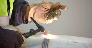
During the GMAW process, the welder strikes an arc between the wire electrode and the workpiece by taking the wire electrode tip nearer to the workpiece surface and pressing the trigger. Pressing the trigger puts the current on, moves the wire electrode, and spray the shielding gas. The heat generated by the arc melts the workpiece surface, wire electrode and forms a molten weld pool, and the shielding gas shields this weld pool to protect it from oxidation /contamination from the atmospheric air.

In the GMAW process, the welder work is much less than the SMAW process since maintaining a correct arc and feeding the electrode wire is taken care of by the machine. The welder has to place the welding gun in a proper orientation concerning the welding area and then move the welding gun along the welding length. The welder needs to clean the nozzle of the welding gun periodically to remove any spatter sticking on it. The welder must also know the voltage, wire feed rate, and gas flow rate adjustment according to the workpiece material and wire diameter. Even when the GMAW is done manually, it is described as a semi-automatic process since the feed and travel speed of the wire electrode, and arc length are controlled by the welding machine. However, the position of the wire electrode (with respect to the workpiece) and the welding speed are under the control of the welder.
When welding in vertical position or overhead weld joints, the welder may have to use a technique such as weaving to ensure proper weld deposition and penetration. In this kind of welding, the gravity force may cause the molten metal to run out of the pool, resulting in a weak weld. The weaving technique varies the zone/point of fusion and limits the volume of metal deposition at a single point. The welder may have to master his technique for quality welding for welding vertical or overhead weld joints. It is a good practice to do the welding in a direction away from the lead connection. The location of the wire electrode in relation to the weld joint is essential and has a bearing on weld penetration, fusion, and weld bead quality.
DCEP (reverse polarity) is the general power source used in the GMAW process. Many metals such as carbon steel (low and medium), stainless steel, and nonferrous metals like aluminum, copper, bronze, etc., can be welded by the GMAW process. The material of the wire electrode depends on the workpiece material.
GMAW is a versatile process, and it is suitable for welding both thin sheet and thick metals. Both metal inert gas (MIG) and metal active gas (MAG) welding are GMAW processes that use the heat generated by the DC electric arc between the wire electrode and the workpiece to create a molten weld pool that forms a weld joint after cooling. A protective gas shields the weld pool jetted out from the welding torch. It is normal to classify both MIG and MAG welding under the gas metal arc welding (GMAW) process. Then what is the difference between MIG and MAG? The difference lies in the gas used for shielding.
Metal inert gas (MIG) welding uses only an inert gas like argon or helium or a mixture of argon or helium for shielding. These inert gasses usually are used for MIG welding of nonferrous metals like aluminum. Metal active gas (MAG) welding uses pure carbon dioxide (CO2) or a mixture of argon, carbon dioxide (CO2), and oxygen as a shielding gas. Carbon dioxide is called active gas since apart from acting as a shielding gas, it helps faster welding. MIG/MAG welding can be made entirely automatic by using robotic movements.
The transfer of the metal from the wire electrode into the weld pool can be done using different methods during the welding. This will be discussed in the subsequent paragraphs.

Quality issues in the GMAW process
Two quality issues occur in the GMAW process, and they are dross and porosity. Dross is a general problem faced in GMAW of aluminum. The problem comes from aluminum oxide or aluminum nitride particles present in either the wire electrode or workpiece materials. Wire electrode and workpiece should be brushed with a good wire brush or chemically cleaned to remove the acid from the surface. If the weld pool comes in contact with oxygen (oxygen in the shielding gas or the atmospheric air), this may cause dross. Hence GMAW welding in outside location (moving air) is to be avoided.
The main cause of porosity in the GMAW process is the entrapment of gas in the molten weld pool, and this may happen if the weld pool solidifies before the escape of gasses. This gas may come from impurities in the shielding gas or on the workpiece. Usually, the quantity of gas entrapped directly relates to the cooling rate of the weld pool. Aluminum has a higher cooling rate, and hence the risk of porosity is more. The workpiece and the electrode should be clean, maintaining moderate welding speeds and setting the current correctly to minimize the porosity.
How is MIG welding different from GTAW/TIG welding?
When you think of MIG and GTAW (gas tungsten arc welding) processes, one typical question comes to your mind, both MIG and GTAW uses argon as an inert shielding gas, then why two separate processes. Well, the reasons are many, and the same are explained below.
- MIG welding is not considered as clean as the GTAW process.
- The stability of the arc (the gap between the electrode tip and the workpiece) is better in the GTAW process. The length of the welding arc is relatively more for MIG compared to GTAW.
- The stability of the arc is better for GTAW (compared with MIG) since the non-consumable tungsten electrode emits electrons easily.
- Even though the shielding gas used in MIG and GTAW is the same (argon), the effectiveness of the shielding depends on the stability of the welding arc and the length of the arc. The length of arc in GMAW is relatively longer than that in GTAW and hence has less stability compared to GTAW arc.
- Also, the stability of the arc depends on the electrode used (GTAW uses a non-consumable tungsten electrode, and GMAW uses consumable filler wire). Consumption of the electrode during welding marginally decreases the stability of the arc.
Therefore, MIG welding is similar to GTAW welding, and one significant difference is MIG welding has a system for automatic feeding of the wire electrode. Due to this, MIG welding offers a higher weld deposition rate, quality weld joints, and these qualities make MIG a preferred process for industrial applications.
Equipment used in gas metal arc welding
The gas metal arc welding (GMAW) process has the following equipment and accessories:
- Power source.
- Shielding gas.
- An automatic wire electrode drive mechanism.
- Electric cables.
- Welding torch/gun.
- Clamp for connecting the workpiece to the power source and wire brush.
- Welding shield.
- A cooling system may be required for the welding gun.

1. Power source
GMAW/MIG process typically uses a constant voltage power source. However, a constant current power source may also be used. The selection of the power source (constant voltage or constant current) depends on:
- Electrode diameter.
- Workpiece material.
- Required wire electrode extension (stick out).
A constant voltage power source is helpful for GMAW when the size of the electrode is less than 2.4 mm, and for a higher diameter wire electrode constant current power source with a variable speed wire electrode feed unit is used. Generally, a direct current (DC) source is used, and most of the time, the wire electrode is positively charged (DCEP). Alternate current (AC) is not preferred for GMAW/MIG welding, and the reasons are the welding arc goes off at each half cycle since the current is reduced to zero, and the arc may not reignite if the cathode cools down.
DCEP polarity is preferred over DCEN for the following reasons:
- Stability of the arc.
- Good metal transfer.
- Less spatter.
- Smooth weld bead across a range of welding currents.
On the other hand, DCEN results in:
- Unstable and irregular arc.
- Short-circuiting of arc.
- Less penetration.
- More heat concentration with the wire electrode (high melting rate).
2. Shielding gas
It will be discussed at length in the subsequent paragraphs.
3. Automatic wire electrode drive mechanism (feed system)
This system ensures the supply of the wire electrode to the welding torch at the required/set speed. The automatic wire electrode feed system can be an independent and separate unit or housed in the power source unit. Housing this unit in the power source unit makes the GMAW more compact. Usually, the wire electrode feed unit supplies the wire electrode at a constant feed rate; however, modern feed units can vary the feed rate to suit the voltage and the arc length.
4. Electric cables
The cables connect the welding torch and the workpiece to the respective terminals of the power source. A separate earth lead may be required to protect the welder and others from accidental shocks. The external protection (sheath) on the cable wire should be able to withstand the current, normal wear, dust, oil, and water, and the diameter of the cable depends on the current it carries (higher the current and duty cycle, the larger the diameter of the cable). The cables can be carrying copper or aluminum wire strands.
5. Welding torch or gun
The crucial parts of your GMAW/MIG welding gun are:
- A contact tip (the wire electrode comes out of it).
- A control switch.
- A nozzle for the shielding gas.
The welding gun is connected to the power source by a cable and to the shielding gas cylinder by a hose. When you press the trigger on the welding gun, it starts the wire feed system, flow of current and the shielding gas, and an arc can be struck by moving the wire electrode nearer to the workpiece surface.
The contact tip is made of copper that is connected to the electric power source and transfers the electric current to the wire electrode. The copper tip should be in good condition and should be replaced when worn out. The wire electrode is automatically fed into the welding gun. It is guided into the copper tip through a guide (to eliminate buckling of the wire), and when the wire comes in contact with the copper tip, it gets connected to the electric source.
The gas nozzle sprays the shielding gas uniformly over the weld pool. Uneven or insufficient gas flow may not be able to protect the weld pool from atmospheric air, and hence selection of the proper size of the nozzle is essential. A higher current welding process creates a bigger molten weld pool and hence needs more shielding gas.

The design of the welding gun may have a provision for compressed air/water circulation to cool the gun. The welding gun described above is called semiautomatic type and is used for semiautomatic (manual) GMAW welding. The other type is an automatic welding gun used for fully automatic GMAW welding.
6. Welding shield and other accessories
The welding shield is available in different forms, such as a hand-held welding shield, welding shield strapped to the welder’s head (can be flipped back when not in use), or a welding helmet with a flip-able welding glass. Other accessories required are a clamp (C-type or any suitable type) to connect the workpiece to the power source, and wire brush (to clean the weld bead), and welder safety gear.
Electrode and shielding gas used in GMAW
A. Wire electrode used in GMAW
The metallic wire electrode is made of an alloy. The alloy composition depends on the composition of the workpiece metal, the welding parameters, the type of welding, condition of the workpiece surface, etc. Proper selection of the wire electrode influences the mechanical properties of the weld metal and weld quality. The wire electrode used in the GMAW process is a continuous wire fed through the welding gun, and there is a wire feed mechanism to ensure the required feed rate. The wire electrode is sometimes called a MIG wire.
The standard expectations from a wire electrode are:
- The weld metal should have mechanical properties equivalent to or better than the workpiece material.
- No welding defects.
Many commercial branded wire electrodes have deoxidizing metals such as silicon, titanium, aluminum, etc., in minimal percentages to prevent porosity due to oxygen. They may also contain de-nitride metals (titanium /zirconium) to avoid porosity due to nitrogen.
Maintaining a constant gap between the wire tip to the workpiece surface is important (stick-out distance); excessive stick-out distance can cause premature melting of the wire, causing spitting arc and sometimes cause rapid dispersing of the shielding gas, resulting in bad weld quality. The less stick-out distance can increase the spatter build-up in the welding torch copper tip. Stick-out distance differs for different GMAW processes. The wire electrode and welding voltage feed rate depending on the electrode wire size and the workpiece/wire material.
B. MIG Welding Shielding gas
Shielding gas is an essential part of the GMAW process. Apart from shielding the weld pool from atmospheric air, it performs other vital functions such as forming an arc plasma, stabilizes the arc on the workpiece surface, and ensures the perfect transfer of droplets from the wire tip into the weld pool. Suppose the molten weld pool is exposed to oxygen and nitrogen. In that case, they can cause fusion defects, porosity in the weld, and weld metal embrittlement (makes the material brittle), if the wire electrode, or the welding arc, or the molten weld pool comes in contact with them.
Hence the shielding gas has a significant effect on the stability of the arc, transfer of metal from the wire electrode tip to the weld pool, and the performance of the weld pool (importantly, its penetration). The normal shielding gasses used in the GMAW process are pure argon or helium, pure carbon dioxide, mixtures of argon, oxygen, and carbon dioxide, and special gas mixtures that may contain helium.
MIG welding uses inert gasses like pure argon or helium, a mixture of argon and helium, and sometimes a mixture of argon, helium, and a very small percentage of hydrogen. MAG welding uses pure carbon dioxide and a mixture of gasses which includes carbon dioxide. MAG is typically used for welding steel.
The selection of the shielding gas for Gas Metal Arc Welding depends on the type of material being welded and the welding process parameters. Pure inert gasses such as argon and helium are used when welding nonferrous metals (like aluminum). When welding steels, the inert gas argon does not give sufficient weld penetration, and helium gives an erratic arc and boost spatter. The high cost of argon or helium makes the low-cost pure carbon dioxide a preferred choice. Using pure carbon dioxide as the shielding gas for steel permits deep penetration welds but increases the oxide formation that harms the mechanical properties of the weld metal, and it cannot be used for welding thin workpieces. To minimize the negative issues, a mixture of carbon dioxide (CO2) and argon (75% CO2 and 25% argon (75/25 welding gas) or 90% CO2 and 10% argon) are typically used in MAG welding.
For short-circuit metal transfer process, a higher carbon dioxide content increases the heat at the weld pool (all other parameters such as voltage, current, wire size, and wire metal being the same). The spray-type metal transfer becomes problematical when the carbon dioxide content exceeds 20%. Carbon dioxide is not used for the open arc metal transfer (pulsed/spray) methods due to increased back-plasma forces. Argon-based gas containing oxygen or carbon dioxide is usually used.
Another combination is a mixture of argon with other gasses such as oxygen, helium, and nitrogen. Excessive oxygen can make the shielding gas oxidize the electrode, leading to weld porosity (if the wire electrode does not have adequate deoxidizers). A mixture of argon and helium is highly inert and is suitable for welding nonferrous metals. A helium content of 50 to 75% increases the voltage required and increases the arc’s heat (due to the high ionization temperature of helium). Sometimes hydrogen (up to 5%) is added to the argon when welding nickel and thick stainless steel workpieces.
The shielding gas flow rate depends on different factors like current, type of gas, weld speed, method of metal transfer, etc. Faster weld speeds and higher current need a higher flow of shielding gas.

Methods of transfer of metal in Gas Metal Arc Welding process
The method or manner by which the metal is transferred from the wire electrode into the weld pool governs the process’s working. There are five major methods of metal transfer, and they are:
- Globular.
- Short-circuiting (dip).
- Spray (droplet).
- Pulsed spray.
- Cold metal transfer.
1. GMAW Globular transfer method
GMAW process with the globular metal transfer method is not the preferred method because it tends to produce high heat, poor weld surface, and spatter. This is a cost-effective method since it uses carbon dioxide as the shielding gas (less expensive compared to argon or helium). Added to this globular method has a high weld deposition rate and allows a welding speed of up to 110 mm per second.
As the welding progresses, a ball of molten metal tends to build up at the tip of the wire electrode, and the shape of the ball may be irregular and bigger than the wire diameter. When the molten ball finally detaches from the wire (due to gravity or short circuit), it drops into the weld pool, leaves an uneven surface, and spatters. Due to the formation of large droplets, this process is usually limited to flat and horizontal welds involving thicker workpieces.
2. GMAW Short-circuiting transfer method
In this method, the current is less than the globular method. Due to the low current, the generation of heat for the short-arc is significantly reduced, enabling the welding of thinner metals (also decreasing the distortion and residual stress in the weld area). The formation of the molten droplets is similar to globular welding; however, instead of dropping into the weld pool, the droplets bridge the small gap between the tip of the wire and the weld pool. This causes a short circuit, and the arc goes off momentarily. But the spark is quickly reignited since the surface tension of the weld pool pulls down the molten metal ball from the wire tip. This process may happen about 100 times per second. This method produces better weld quality, less spatter than the globular method, and welding is possible in all positions. However, the weld deposition is slower than the globular method.
In the short-circuiting (dip) method, the molten metal formed on the tip of the wire reaches the weld pool when the wire dips into the weld pool. Short-circuiting (dip) method can be achieved by setting a low voltage (for a wire diameter of 1.2 mm, the arc voltage is 17 V (100 Amps) to 22 V (200 Amps). Due care is essential when setting the voltage and inductance in relation to the speed of the wire feed to minimize the spatter.
3. GMAW Spray transfer method
The spray transfer method suits well for the welding of aluminum and stainless steel, and inert gas should be employed as shielding gas. In this process, the metal from the electrode wire is swiftly transferred along the stable arc into the weld pool, resulting in a good quality weld finish without spatter. As the current value exceeds the range of short-circuit transfer, the metal transfer from the electrode wire changes from large globules to small drops in the form of a vaporized spray. This process needs a higher current and is suitable for workpiece thickness 6.4 mm and above.
For the spray (droplet) method of metal transfer, a higher voltage is required to ensure the electrode wire does not make contact with the weld pool (that is, avoid ‘short-circuiting) (for an electrode wire diameter of 1.5 mm, the approximate range of voltage can be 27 V (250 Amps) to 35 V (400 Amps). Also, due to the bigger size weld pool, this method usually is suitable for flat and horizontal welding positions and occasional vertical down welding.
4. GMAW Pulsed spray transfer method
This is a variation of the spray transfer method based on the spray transfer, but by using a pulsing current to melt the electrode wire and only one droplet of the molten metal is allowed to drop for every pulse. The pulsing current keeps the average current lower, reduces the overall heat input, and, hence, a smaller weld pool and heat-affected zone. All this makes it possible to use it for welding thin workpieces. This method provides a stable arc, and there is no spatter. The smaller weld pool makes this process more versatile, and the advantage is it can use higher size electrode wire and can be used for welding in all positions.
5. GMAW Cold metal transfer method
For the welding of thin metals, the cold metal transfer method is used by reducing the current (compared to the short-circuiting method). This method produces many molten metal drops per second and can be used for welding aluminum.
Factors affecting GMAW welding
The factors/parameters affecting the GMAW welding are:
- Welding current.
- Wire electrode angle.
- Wire extension.
- Welding voltage.
- Travel speed.
- Type of shielding gas.
1. Welding current
DCEP usually is used in MIG welding. The value of the welding current used in MIG affects the penetration of weld, weld deposition rate, weld geometry, and quality of the weld. When you keep all the other welding parameters constant, an increase in the welding current leads to an increase in the depth and width of weld penetration and the weld bead’s size.
Each type of electrode wire and its size has a given range of minimum and maximum current for the best results. Using a current lower than the recommended may lead to poor weld penetration, rough weld bead, etc. Using a current higher than the recommended may lead to undue deep penetration, larger size weld bead, etc.
2. Wire electrode angle
The position of the wire electrode in relation to the weld joint affects the weld penetration and weld bead geometry to an extent higher than that of the arc voltage and wire travel speed. The angle of the electrode wire in relation to the weld joint is called work and travel angles.
3. Wire electrode extension
The wire electrode extension (also called stick-out) is the length of the electrode wire projecting out of the contact tip. This is the length of the electrode wire that carries and conducts welding current. The amount of stick-out affects the weld penetration and rate of metal deposition since stick-out length changes the heating of the electrode due to its electrical resistance.
An increase in the stick-out length leads to an increase in its electric resistance and hence a rise in the temperature of the electrode wire. This temperature may be of a value nearer to the melting point of the wire electrode, and a welding arc of small intensity will be sufficient to melt it. This reduces the weld penetration. The electrode wire diameter and its stick-out length influence the selection of welding current.
4. Welding voltage
The length of the arc is a significant and vital variable in MIG welding, and it should be controlled. When you keep all the other variables such as composition and size of electrode wire, shielding gas, welding technique as constant, then the length of the welding arc is directly related to the arc voltage.
Standard arc voltage in the case of carbon dioxide and helium is considerably higher than for argon. A long arc length disturbs the gas shield, affects the weld penetration and the surface of the weld bead. In MIG welding, the arc voltage has a significant effect on the weld penetration and bead geometry. When you increase the arc voltage, the weld bead becomes flatter and wider, and the weld penetration increases (this may continue till an optimum value of voltage is reached and then it stabilizes). The high voltage causes more spatter and porosity, while the low voltage leads to narrow and convex weld beads (very low voltage leads to spatter and other defects).
5. Travel speed
The travel speed indicates the speed at which the arc travels along the weld length. This is under the control of the welder in semiautomatic MIG welding and under the control of the machine/robot in automatic MIG welding. The influence of the travel speed can be compared to the arc voltage (or current). An increase in travel speed reduces the weld penetration and increases the weld bead size.
6. Type of shielding gas
As we have already seen in detail, the selection of the shielding gas influences the welding speed and weld quality.

GMAW safety considerations
Arc welding, whether SMAW or GMAW, can be dangerous if necessary safety precautions are not taken. A welder has to deal with electric current, electric arc, hot components, welding fumes, thermal radiations, etc. He/she must take all the safety precautions and wear safety gear for protection. A welder has to wear leather hand gloves, long sleeve jackets, shoes, good quality welding helmets (with flip-able welding glasses), and a mask (if there is no provision of built-in protection from fumes in the helmet).
The welding enclosure should have good ventilation for the quick exit of the toxic gases formed during welding. Also, the welding enclosure must not contain inflammable/combustible items like fuel, oil, paper, etc. Often, the welder works sitting inside a confined portion of the part being fabricated, such as a boiler, tank, shipbuilding, etc. In such cases, proper ventilation is crucial for the safety of the welder.
Conventional standard welding helmets have dark plates on the front to prevent exposure to thermal radiation. The latest helmet designs have a liquid crystal-type faceplate that automatically darkens when exposed to the welding arc. The place of MIG welding should have a suitable fire extinguisher nearby.
Advantages and limitations of the GMAW process
Advantages
- GMAW/MIG welding can produce high-quality welds faster than SMAW and GTAW processes.
- Application of shielding gas (instead of a flux coated electrode) ensures no scope for entrapment of slag in the weld metal.
- The shielding gas protects the welding arc and the molten weld pool to ensure minimum loss of alloying elements and also good-quality welding.
- GMAW/MIG is a very versatile process and can be used for a variety of nonferrous and ferrous metals such as aluminum, copper, nickel, and their alloys, and ferrous metals iron, steel, stainless steels, etc.
- GMAW/MIG can be operated both as semiautomatic, automatic type, enhancing the rate of productivity and ensuring good quality.
- GMAW/MIG can be adopted for robotic welding automation.
- GMAW/MIG can be used for a wider range of workpiece thickness.
Disadvantages
- GMAW/MIG is not preferred for vertical or overhead welding positions due to its high heat input and bigger molten weld pool.
- The equipment is complex when compared to the SMAW process.
- The use of inert gases like argon and helium makes the process expensive.
- GMAW process cannot be used in an open area since the volatile moving air affects the shielding gas protection.
Application of Gas Metal Arc Welding process
Gas Metal Arc Welding process is very versatile, and the applications are:
- Gas Metal Arc Welding process can be used for welding a variety of nonferrous and ferrous metals such as aluminum, copper, nickel, and their alloys, and ferrous metals iron, steel, stainless steels, etc. This versatility makes it a preferred process in most of the engineering industries.
- GMAW process can be easily automated and is adaptable for robotic welding, and is very popular in mass production industries like the automobile industry and consumer goods industry.
- GMAW process due to its ability of welding across different thicknesses (thin and thick metals), is used in the manufacture of railway coaches and light, medium, and heavy steel fabrications.
- The ability to weld both ferrous and nonferrous metals, faster welding, and good quality welds makes it suitable for the aircraft manufacturing and aerospace industry.
GMAW vs. SMAW, advantages, and disadvantages
| No. | Gas metal arc welding (GMAW) | Shielded metal arc welding (SMAW) |
| 1 | Higher initial cost towards equipment (compared to SMAW). | Lower initial cost towards equipment. |
| 2 | Higher operation cost (compared to SMAW) is due to the shielding gas and the welding wire (electrode). | Low operation cost since the process does not need a shielding gas. |
| 3 | GMAW process uses a bare continuous wire as the electrode, and some category of welding wires has an anti-corrosion coating on the wire. | SMAW process uses a flux coated electrode. |
| 4 | A shielding gas like argon, helium, or carbon-di-oxide (or a mixture of gasses) is delivered from the welding torch during welding to protect the arc and the molten weld pool from atmospheric oxidation and contamination. | The flux coated on the electrode burns along with the electrode and gives necessary shielding gas to protect the arc and the molten weld pool from atmospheric oxidation and contamination. The flux leaves a slag on the weld bead, which the welder should chip off immediately. |
| 5 | There is no flux, and hence no slag, and no chances of slag inclusion in the weld metal.
|
The slag left by the flux coating protects the weld from atmospheric gasses, but there are chances that slag may get into the weld metal leading to welding defects. |
| 6 | Less versatile and welding in all positions is not preferred. | SMAW is highly versatile and can be used for welding in all positions. |
| 7 | GMAW can be easily automated with less human involvement. Hence, minimum human errors. | SMAW is a manual welding process, and automation is not possible due to the short length of the welding rod. Scope for human errors exists. |
| 8 | The welding wire is fed through a device into the welding torch, and the wire is fed continuously (without interruptions). Hence, the productivity rate is better than SMAW. | The welder has to hold the electrode in his hand and feed it during welding and has to interrupt in between to change the electrode. Hence, the productivity rate is low. |
| 9 | GMAW process does not leave a slag. Normally, secondary operations are not required to improve the welding bead. | SMAW process leaves behind a slag that the welder has to chip off. The secondary operation may be required to improve the welding bead. |
| 10 | GMAW process cannot be used in an open area since the volatile moving air affects the shielding gas protection. | SMAW process can be used in an open area. |
Conclusion
GMAW process, due to its speed, quality, and versatility, is very popular in engineering industries and light, medium, and heavy fabricators. Due to the research and development of this process, GMAW will achieve higher quality, productivity, and versatility in the days to come.
References: