Carburetor is the device that mixes a specific amount of fuel is with a specific amount of air for fast and thorough combustion, which generates the impulse given to the engine piston at the beginning of the power stroke. The mixture is generated under rigorous conditions and by observing exact proportions. That whole process is known as the carburation process.
The carburetor is supplied by the gasoline supply system and into which atmospheric air is drawn by the vacuum created by the piston’s downward motion during the intake stroke. The fuel, driven by the airstream, divides into fine droplets, which are then atomized by the impact against the air on which favors fuel vaporization, thus preparing the formation of a homogeneous mixture.
Carburation Process Conditions
For proper execution of a carburation process, it is must meet the following conditions:
- A mixture of the right amount of fuel with the right amount of air for fast and thorough combustion; the fuel and air mixture ratio is called the fuel-to-air ratio.
- Fuel and air must be in the same physical state (gaseous) to mix. Therefore, if the fuel is liquid, it must be changed into gas: this process is called vaporization.
- Since oxygen molecules must surround each molecule of fuel to burn; the mixture must be perfectly homogeneous.
- The fuel/air ratio must be adapted to all engine speeds without external action, adapted automatically.
- The carbureted mixture must be evenly distributed among all cylinders.
Gasoline Vaporization
For fuel and air to mix, they must be in the same physical state: the gaseous state. If the fuel is liquid, it must be changed into gas; this transformation is called vaporization.
The following factors are involved in gasoline vaporization:
- The “air/gasoline” contact surface. The air/gasoline contact surface must be as large as possible; for this, the gasoline is supplied at a high velocity through a very small port and collides with the airflow in which it atomizes into fine droplets “atomization.”
- The pressure. At a given temperature, a liquid vaporizes faster when the pressure is low “vacuum.”
- The temperature. At a given pressure, vaporization is favored by heating the liquids; at boiling temperature, vaporization is particularly fast “re-heating.”
- The heat supplied. Vaporization absorbs heat; reheating is necessary to maintain the temperature.
As mentioned above, the pressure must be low; this creates a crucial vacuum in the carburetor. The larger the volume created by the engine pistons and the smaller the cross-sectional area for air suction passage, the greater the vacuum. With the significant pressure decrease, vaporization begins.
A venturi is placed in the carburetor to increase the airflow velocity and facilitate vaporizing.
The carburetor’s second function is to decrease the pressure and thus obtain spraying and atomizing gasoline through a calibrated port called a jet.

Carburetor Function and Construction Parts
The carburetor is designed to ensure the mixture of air and gasoline in conditions permitting correct carburation at all engine speeds. In addition to carburation, the carburetor provides the regulation, which means matching the power developed by the engine to the power required.
A basic carburetor divided into three assemblies:
- The constant-level tank.
- The jet.
- The carburation chamber.
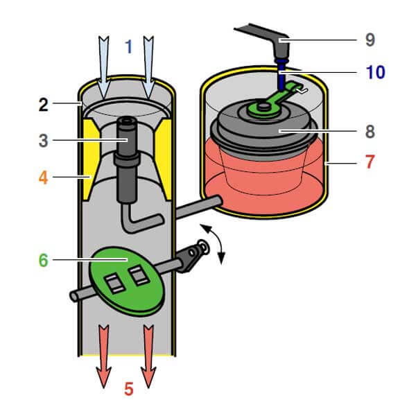
1: Air inlet – 2: Barrel – 3: Jet – 4: Venturi – 5: Mixture of air and gasoline to cylinders – 6: Butterfly valve controlled by the accelerator – 7: Constant-level tank – 8: Float – 9: Gasoline inlet – 10: Needle
Carburetor Constant-level Tank
A reserve called a constant-level tank is provided with a needle valve actuated by a float. The gasoline is delivered from the tank by gravity or through a pump at low pressure.
When the gasoline in the tank is at the required level, the rising float actuates the needle that closes the inlet.
As soon as the fuel is being consumed, the needle opens until the level required in the tank is obtained. A vent in the tank enables gasoline to be discharged under the action of the atmospheric pressure.
Carburetor Jet
The jet is fed from the constant-level tank. It is provided with a calibrated port; at the outlet of this port, the jet of gasoline atomizes in the airstream; this flow orifice is located a few millimeters above tank level.
Carburation Chamber
The carburation chamber includes:
- Venturi: The venturi is designed to reduce the air circulating pressure in the carburation chamber to drop at the jet’s level. This creates a vacuum area, the vacuum being proportional to the velocity of the airflow. The strongest vacuum is recorded slightly downstream from the narrowest point, at a distance that corresponds to one-third of the venturi diameter. The venturi has a particular profile, the upstream angle being wider than the downstream angle.
- The gas throttle valve: The obturator or throttle valve is located downstream from the carburation chamber; it is designed to regulate the engine power by limiting the amount of gas allowed by varying the gas flow cross-sectional area.
- Pipe section: The pipe section running between the jet and the intake valve.
Carburetor Operation
Gasoline is delivered into the Constant-level tank by gravity or through a pump. As gasoline is discharged into the tank, the buoyancy increases under the float. When it is equal to the float’s weight, the latter is in equilibrium and floats: the gasoline keeps on flowing. The level increases, and the float rises until the needle comes into contact with its seat. The gasoline keeps on flowing into the tank due to pressure “pressure head or pump pressure.”
As the gasoline level in the tank rises, the pressure under the float increases until it exceeds the gasoline inlet pressure. At this moment, the needle which adheres to its seat closes the gasoline inlet. When the jet feeds the carburetor, the gasoline level in the tank decreases, the float descends, allowing the gasoline to flow into the tank again until the required level is reached and the gasoline inlet is closed.
The gas throttle valve is actuated to either reduce or increase the power developed by the engine. The pressure upstream from this valve remains equal to the atmospheric pressure when the choke flap is closed. The more the choke flap obstructs the gas passage, the lower the downstream pressure; this device’s obturating action causes head losses in the gas flow.
Consequently, intake gases are admitted at varying pressures and therefore in varying masses. The control is quantitative. Power is changed by acting on the filling index and subsequently on the compression pressure.
When the engine stopped
The intake pipe and tank are under atmospheric pressure; the gasoline is delivered until the needle closes its inlet. As in the tank, the level in the jet is constant.
When the engine is running
The immobilization of the gas throttle valve in a medium position generates an airstream in the intake pipe. The gas supply to a single cylinder is periodical: it occurs during a single stroke out of four in a four-stroke engine.
Several cylinders are fed from the same carburetor; therefore, throughout the combustion chamber’s common part, the gas flow does not vary significantly during the operation.

Types of carburetors
According to the position of the carburetor barrel and the direction of the gas flow, we can distinguish three types of carburetors:
- Updraft carburetor for upward flow.
- Transverse draft carburetor for horizontal flow.
- Downdraft carburetor for downward flow.

1. Automatic Carburetor
An automatic carburetor is a carburetor providing a constant mixture ratio when the engine is run at economical speed and a varying ratio for the mixture to be enriched when the engine power must be increased.
The mixture ratio can be varied by acting on the air flow rate or the gasoline flow rate. Since the gasoline flow rate increases faster than the airflow rate, it is possible to:
- Reduce the gasoline flow rate.
- Increase the air flow rate.
Three types of methods to correct the changes in the ratio of the air/gasoline mixture as follows:
A. Air adjustment methods; “acting on the air (air flow rate must be increased).”
The air adjustment method is also called the secondary air principle. It is no longer used. A vacuum-controlled additional amount of air is delivered to correct the over-richness of the mixture. It is controlled by a weighted valve, which opens when the vacuum reaches a specific value when the air/gasoline mixture contains too much gasoline.
B. Gasoline adjustment methods; “acting on the gasoline (gasoline flow rate must be decreased).”
This result is obtained through the combination of the following devices:
- Flooded jet.
- Diverted jet and emulsion tube.
- Addition of a compensator jet.
Flooded jet
As the air and gasoline flow rates vary with the vacuum, the carburetor’s main circuit must be provided with an automatic metering device that includes a flooded jet.
The latter plays a significant role when the engine is running at low speed. The jet is placed below the carburetor float chamber level (in practice, at the bottom of the float chamber). Under the vacuum effect, which adds up to that of the level difference, it delivers the gasoline. When the speed is increased, the vacuum increases, and the impact of the level difference becomes negligible.
Diverted jet and emulsion tube
As the air and gasoline flow rates vary with the vacuum, the carburetor’s main circuit must be equipped with an automatic metering device, including a diverted-jet system and an emulsion tube.
The diverted-jet system is designed to reduce the vacuum affecting the jet when the vacuum is average or great to decrease the gasoline flow rate. When the vacuum is small, the jet delivers according to the flooded jet principle: the mixture is rich.
The emulsion created increases the air passage cross-sectional area in the diverted-jet system in relation to the vacuum. In this manner, the gasoline flow rate can be monitored in relation to the airflow rate to comply with the ideal ratio curve.
Addition of a compensator jet.
In a basic carburetor, the gasoline flow rate increases faster than the airflow rate. It is, therefore, possible to associate a jet called a compensator jet with the main jet. Its flow rate corrects for the enriching effect of the basic carburetor. In this way, an adequate ratio can be obtained at all speeds.
The jet flow rate must weaken the ratio of the air/gasoline mixture when the speed increases.
For this, the compensator jet flow rate must vary in a direction opposite to that of the main jet.
C. Combined methods; “acting on gasoline and air.”
2. Solex Carburetor

Many types of Solex carburetors; are characterized by the possibility of adjusting components, such as the main jet or operating jet, the diverted jet system (variable), the venture, and the idle circuit.
Solex carburetors’ operation is based on the principle of the flooded diverted jet system with multi-stage emulsion. As the vacuum increases:
- The gasoline at the emulsion tube level flows into the carburation chamber in the form of a rich mixture.
- The level decreases, uncovering the highest holes of the emulsion tube.
- The mixture weakens progressively, and the air passage cross-section in the diverted system increases.
When all the holes are uncovered, the jet diverted system’s action is maximum, and the richness of the mixture is maintained at values approaching the air/gasoline mixture ratio, which provides the highest efficiency.
3. Stromberg Carburetor

In Stromberg carburetors, the metering of the mixture is ensured at various speeds through:
- A flooded main jet.
- A perforated emulsion tube.
- A diverted air calibrated orifice.
Idling is ensured by an auxiliary air jet. Adjustment is made through a screw acting on the air jet. A mechanically-controlled piston pump ensures pickups. This pump enables the carburetor to operate at two speeds: very high speed or economical speed.
This device enables the engine to develop extra power at high speeds by enriching the mixture obtained by two jets delivering simultaneously.
4. Weber Carburetor
To overcome the problems encountered with increasingly powerful engines (incompatible operation at high and low speeds), twin-barrel carburetors are substituted for conventional carburetors. They are of two types: carburetors with simultaneous opening of throttles and carburetors with staggered opening of throttles.
Carburetors with simultaneous opening of throttles

Carburetors with throttles opening simultaneously can be compared to separate carburetors operating at the same time and in an identical manner. This system’s advantage is a better filling of the cylinders, a better distribution of the mixture, and therefore improved pickups and higher speeds.
This type of carburetor’s lack of flexibility is a drawback that does not exist with the other type.
Carburetors with staggered opening of throttles

Carburetors with staggered opening of throttles include:
- The primary barrel whose characteristics permit engine running at low economical speeds.
- The secondary barrel opens only when the accelerator is at a specific position and enables the engine to develop maximum power.
A series of levers open this gas throttle.

5. Zenith Carburetor

Changes in the mixture ratio can be corrected for by acting on the flow of gasoline. It is done through an automatic metering device provided with a compensator jet and fitted in the main circuit.
The adjusting elements are the main jet, the idle jet, the venture, and the compensator jet, which is immersed and therefore not subjected to the action of the vacuum prevailing inside the venturi. Since its flow rate is the same at all engine speeds, the mixture’s richness varies inversely to the speed.
6. Constant-vacuum Carburetor

In order to approach the ideal air/fuel ratio curve, the partial vacuum can be kept constant by varying the degree of throttle opening or the venturi throat area. A constant-vacuum or variable-jet carburetor is thus used.
For a constant flowrate, the airflow speed is inversely proportional to the area of the air passage.
It is necessary to increase the air passage area proportionally to the gaseous fluid flow rate for a constant flow speed. The resulting partial vacuum is constant at any speed.
A slide valve or sliding piston moves perpendicularly to the gas flow. Its movement is directly controlled by the vacuum in the venturi throat and is obtained through a spring and a diaphragm.
Carburetor vs. Fuel Injection
Carburetors have the following disadvantages:
- The ideal fuel (gasoline)/air ratio curve is not accurately adhered to.
- As the air and gasoline gas molecules flow through the manifolds to be mixed, they expand, reducing the carburetor’s volumetric efficiency.
- Vaporation, due to pressure decrease at the throttle, causes the carburetor to freeze.
- At a cold temperature, part of the gas condenses on the sides of the manifold. Therefore, a much richer mixture is required.
- Irregular mixture homogeneity increases fuel consumption and pollution levels.
- When there is only one carburetor, there is an irregularity in the distribution of the mixture among the various cylinders.
In the injection system, the air is introduced into the engine through an intake manifold of a large cross-sectional area. A mechanical or electric pump pressurizes the fuel, and the exact amount of fuel is introduced into the manifold by injectors at each cylinder.
Fuel injection has brought many improvements, such as:
- The air/fuel mixture is made by taking a larger number of parameters such as engine load, water, air temperatures, etc.
- The carbureted mixture is very homogenous and denser. It is mainly due to the fuel spraying system, the reduced contact time between air and sprayed fuel, and the lower heating temperatures.
- Combustion at any speed is improved by more precise air/fuel mixing ratios.
- Better volumetric efficiency results in increases in torque and power.
- Fuel consumption and pollution levels are reduced.
- Engine flexibility is improved due to even combustion in the different cylinders.
Read: What You Need To Know About Turbocharger And Supercharger
References:
- Wikipedia– Carburetor.