Bollard Pull Test is the trail performed to determine the static pull or zero speed pulling that a tug can employ in operating conditions; in another term, the bollard pull test is the tractive force of a tug expressed in metric tons (T) or KN. Bollard Pull calculation is essential and one of the most commonly performed tests in marine towing operations to determine the maximum tractive force of the tug engaged in the towing for proper planning and safe operation.
Bollard Pull test is usually conducted in ideal environmental condition or as close to ideal as possible to minimize the external effects that may affect the test result. Hence, the test is typically not performed in normal operation conditions of shallow water, rough sea, high wind, or confined harbor basin as such conditions will not produce steady results.
Bollard Pull Definitions
The most common bollard pull definitions are as follow:
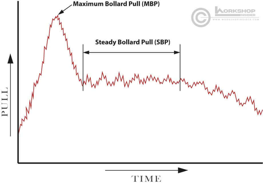
The Maximum Bollard Pull (MBP)
The Maximum Bollard Pull, also called “Static Bollard Pull,” is the maximum recorded tension achieved shortly after the test’s commencement over a period of approximately one minute. Determining MBP takes place with the maximum engine output, optimum propeller pitch, and during working in still water.
The Steady Bollard Pull (SBP)
The Steady Bollard Pull, also called “Continuous Bollard Pull,” is the remaining steady traction force after the performance decreases from the maximum bollard pull force. The performance reduces due to cavitation and propeller slip once the water is streaming through the propeller representing the continuously maintained tension in the towing wire.
The SBP is measured for a period of about 10 minutes and not less than 5 minutes at the times when the tug’s pull and direction are steady.
The Effective Bollard Pull (EBP)
The Effective Bollard Pull is the traction force that the tug can develop in an open seaway. The calculation of EBP is not achievable during the bollard pull test; therefore, the EBP is calculated based on a fraction of the steady bollard pull SBP considering the losses due to environmental and external factors. Typically, EBP is estimated to be 75% of SBP.
Bollard Pull Requirements
For proper testing and reliable results, certain requirements and conditions need to be fulfilled. The main conditions that need to be considered are site condition, vessel (tug) state, and environmental condition.
Site Condition
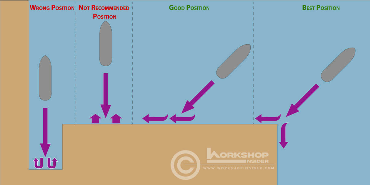
The bollard pull location should be in a clear open water area with no obstructions close to the tug, which may affect the operation. The position of the tug should be appropriately selected to give a clear run for the propeller wake.
The following illustration provides a comparison and recommendation between different locations.
The best jetty to perform the test is the legged jetty with no wall that allows propeller wake to flow under the jetty. However, the test can be performed on a solid wall jetty but considering the tug position as per the above illustration.
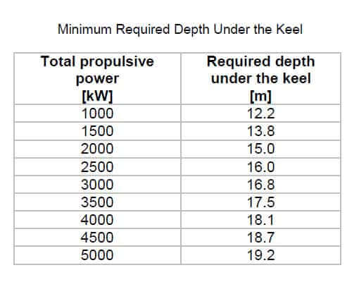
The second important parameter related to the site condition is the water depth; the depth under the tug keel and around it has to be as deep as possible. When performing a bollard pull test in shallow water, the propeller wash and the less amount of water below and around the vessel generate “water circulation.” For a fair bollard pull test result, a build-up of water circulation has to be avoided.
The following table provides the minimum required water depth under the tug keel.
The minimum required water depth should be obtained below the tug keel and within a radius of 100 m from the tug to avoid water circulation.
Vessel Condition
During the bollard pull test, recording the tug’s displacement, draft, and trim is necessary to note in the bollard pull certificate. The tug draft should be as per the tug’s construction waterline level to ensure adequate propellers’ immersion. The trim of the tug should comply with the intended operating trim. Typically, the tug will be trimmed on an even keel or with a stern trim.
Tug deck equipment that will be utilized during the testing, such as towing winch and drum, towing hooks and strong backs, fairleads, etc., must be in good condition and capable of handling the anticipated load of “Maximum Bollard Pull” with suitable safety factor.
The increase of tug’s engine revolutions continues until steady bollard pull readings are reached and maintained on the same range with the main engines at maximum continuous power. Maintaining the tug in the testing position is always challenging, especially if the tug tends to yaw. Tug position correction will require rudder action that affects the testing readings; thus, rudder action should be recorded. During bollard pull testing, shaft revolutions, engine data through, rudder angle indicator, and yaw reading angle should be recorded and synchronized with bollard pull readings.
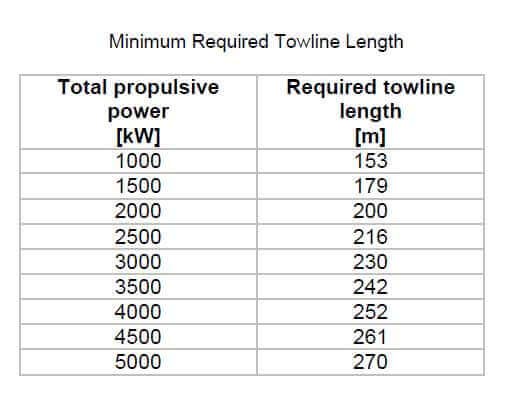
Another essential condition to consider is the towline; to avoid the influence of propeller wake reflected from a solid jetty, the towline should be as long as possible. The following table provides the minimum length of the towline measured between the edge of the jetty and the stern of the tug.
Environment Condition
The wind speed during the bollard pull test should be as minimum as the tug’s performance is not considerably affected. Typically, the maximum wind speed shall not exceed 5m/sec. The test should be stopped and repeated if the wind speed causes the tug to yaw significantly.
The testing should occur in a sea with no current or current that does not exceed 1 knot. The current direction is as important as the current speed; current from astern is acceptable during the test; however, current from the bow or the side is not permitted. Typically, a drop in bollard pull of approximately 4% with every 1-knot increase of current speed from the bow.
Bollard Pull Test Procedure
- The bollard pull test starts with warming up the main engines.
- The test covers a range of different engine powers; however, the test should start with the maximum bollard pull while the test location’s water is still undisturbed.
- The subsequent bollard pull measurements should start after at least 10 minutes to allow the water to settle.
- Monitoring water circulation around the tug during testing is necessary for appropriate readings; the water circulation should not exceed 0.5m/s.
- An electric or electronic dynamometer should be used during the testing to measure bollard pull force.
- The dynamometer should be calibrated before starting the testing; the maximum acceptable deviation within the measuring range must be less than ±2%.
- A mechanical load gauge may be used as an alternative in the case of non-availability of the dynamometer.
- Tug’s towing winch, hook, or towing bit should be utilized to perform the bollard pull test.
- Appropriate inspection of the tug’s deck machinery, which will be utilized during the testing, the test should stop in case of any visual damage or operational malfunction.
- The dynamometer should be positioned at the jetty between the towline and the jetty bollard; however, whenever it is not feasible, the dynamometer may be placed at the tug between the tug’s hook and the towline.
- The connection of the towline between the jetty bollard and the tug should be straight, avoiding the towline to touch the jetty edge as towline touching the jetty will create friction and thus reduce the dynamometer readings.
- In case of a high-level jetty, or for any other location restriction that the towline touching the jetty edge is unavoidable, a roller should be placed under the towline at the edge of the jetty.
- During bollard pull testing, the tug maintains the position without steering. If tug yaws or whenever steering action is unavoidable, the steering action should be kept to a minimum.
- If the tug position changed dramatically for any reason, or in case of violent yaw or steering motions occur during the testing, the test should be repeated.
- Measuring the intermediate shaft torque using a torsion meter is the most recommended and accurate method to determine the actual engine power during the bollard pull test.
- An auto-graphic recorder is used during the test to record the test data.
- If the auto-graphic recorder is not available, the load gauge should be monitored continuously. A data logger should record the maximum and minimum readings in each 30second interval.
- A proper communication channel between the tug and the shore station is mandatory, as the load cell is typically positioned ashore. Communication is usually established by either mobile phones or VHF; however, the telecommunication should ensure that it does not disturb the data logging, and verification should be done before starting the testing.
Estimation of Bollard Pull Value
For a rough estimate of tug bollard pull capacity and approximate conversion from tug’s Break Horse Power (BHP) to effective available Bollard Pull in tons (T), the following formulas may apply:
- Tug with fixed pitch propeller: BHP x 0.9 x 1.10 / 100 = (T).
- Tug with fixed pitch propeller and kort-nozzle: BHP x 0.9 x 1.20 / 100 = (T).
- Tug with controllable pitch propeller: BHP x 0.9 x 1.25 / 100 = (T).
- Tug with controllable pitch propeller and kort-nozzle: BHP x 0.9 x 1.40 / 100 = (T).
The formulas results will provide rough estimates and might be variable.
Bollard Pull Certification
Bollard pull certification is neither a statutory nor classification requirement; the certificate is usually issued to the builder or owner to specify the tug bollard pull capability. The bollard pull capability is necessary for towing planning and calculating the required power-reserve to ensure the tow operation’s safety. Besides, bollard pull is a method of classifying tug boats based on their capacity. Bollard pull certificate is essential to raise the owner’s liability in damage event of a towed object or inability to achieve or maintain a minimum speed needed during towing operation.
The bollard pull certificate will typically take a factual statement on a report form; the report should contain all the relevant information concerning the tug, environmental data, propeller, machinery, instrumentation, and all testing records.
During testing, the tractive force will be recorded to produce the bollard pull curve, a steady bollard pull (SBP) will establish over a selected period of approximately 10 minutes and not less than 5 minutes. The maximum bollard pull (MBP) is the maximum recorded pull force during the testing period. If these values are determined during engine overload conditions, the certificate should contain an appropriate statement of the same.
Similarly, a statement should be made in the certificate whenever any auxiliary machinery driven by the main engine is disconnected during testing. In general, for the purpose of certification, the test should be recording the results while the main engine is developing its maximum continuous power.
Conclusion
A bollard pull test is a trail performed to issue the bollard pull certificate to the builder or owner specifying the tug bollard pull capability. The certificate is neither a statutory nor classification requirement; however, it is necessary for towing planning and calculation of the required power-reserve to ensure the towing operation’s safety.
Tug’s pulling capacity is not accurately determinable by mathematical methods; therefore, it must be evaluated for each tug by a bollard pull test. In exceptional cases performing bollard pull testing is impossible; alternatively, certification of bollard pull is performed based on model testing and theoretical prediction analysis. In such a case, the final certificate will be headed “Certificate of Calculated Bollard Pull”.
References:
- Lloyds register – Bollard Pull Certification Procedures – Guidance Information.
- Steerprop – Bollard Pull Trial Code for Tugs with Steerprop Propulsion.

