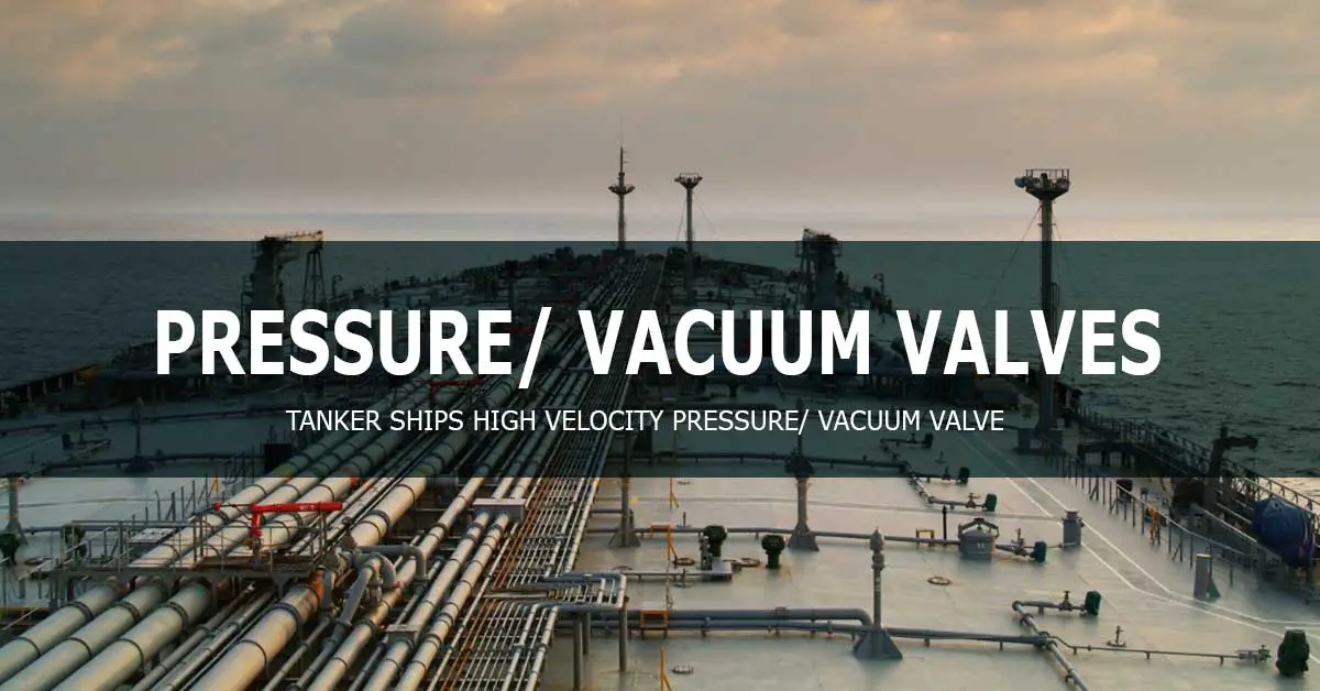
High-Velocity Pressure/ Vacuum or P/V Valve is a valve that provides automatic safety control of pressure differentials during cargo operations and during the voyage to avoid ship’s cargo tanks damage.
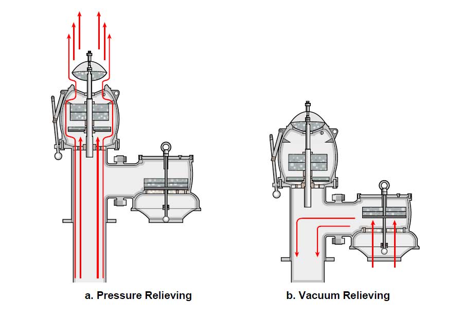
Whenever the cargo tank is over-pressurized above a pre-set level, the release valve opens, ensuring that venting is released at high velocity to avoid gas concentrations on the deck. In the event of low-pressure below a pre-set level, the vacuum valve opens and draws air into the tank through a flame trap. The Pressure/ Vacuum valve ensures that the cargo tank pressure remains within the pre-set operational pressure limits.
Cargo Tank Venting
Tanker ships (crude, chemical, and other tankers) are equipped with venting systems to prevent the ship’s tank from being under or over-pressurized. Two common known types of venting systems are namely “open” and “controlled.” P/V valves are fitted on the controlled tank-venting system.
An open tank venting system is used for cargoes of little or no flammable or toxic hazard.
A controlled tank-venting system is used cargoes emitting harmful or flammable vapors. One or more pressure/vacuum valve is fitted on each cargo tank to relieve overpressure or under pressure.
High-Velocity P/V Valve
Combined Pressure / Vacuum valves are fitted to each cargo oil and slop tank based on the vapor emission control system. The valve operates automatically and carries out the relief function when the tank’s pressure exceeds setting pressure. Before loading, discharging, and ballasting, the valve must be check-lifted to prevent sticking of the valve disc and to ascertain free operating of the valve disc according to SOLAS requirements.
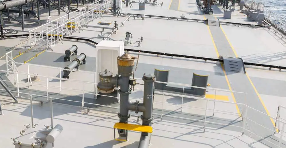
The pressure/vacuum valves are mounted on standpipes at a certain distance above the deck; each P/V valve is connected to its cargo tank through a vent pipe.
High-Velocity Pressure/ Vacuum Valve Operation
Manual Operation
This valve has manual men for check lifting, check the lift handle to monitor the pollution inside the valve, including vapor condensate and condensate residue.
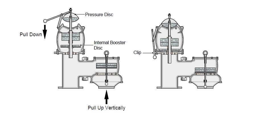
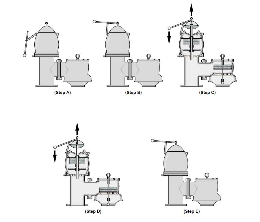
As illustrated above, the manual operation procedure of check lifting for pressure disc is as follows;
Step a: The handle is disengaged from the clip.
Step b: The handle top hook is connected to the lifting bush of the pressure disc.
Step c: The handle is pushed downward.
Step d: The pressure disc is lifted fully.
Step e: By the function of self-closing, the valve closes to its original condition. It is recommended to close the valve carefully and slowly to prevent damage to the disc and seat caused by rapid closing.
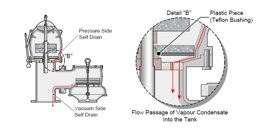
Self-draining
In the event of vapor condensation, the valve lets it drain by its structure that has inclined inside the surface. This self-draining structure is a simple precaution for inoperable such as clogging and sticking.
Adjustment of Setting Pressure
As the Pressure/ Vacuum valve is a weight load type, its pressure setting including pressure and vacuum side is adjusted by deadweight. Thus, to adjust the setting pressure, the valve should be dismantled partially, and deadweight should be added or removed.
The adjustment of dead weight is followed by checking it using a pressure gauge; typically, the process should be performed by a qualified person during the ship’s drydocking or whenever necessary.
Pressure / Vacuum Valve Testing Procedure
The testing should be carried out according to ISO 15364 “Ships and marine technology — Pressure-vacuum valves for cargo tanks and devices to prevent the passage of flame into cargo tanks” or any other related standard.
- Test the pressure and/or vacuum seat leakage three times to verify leak tightness and record all test pressure and vacuum readings.
- Slowly open the test stand pressure test or vacuum test valve (supply pressure).
- Adjust the appropriate flow meter to achieve the specified flow rate as per P/V valve size.
- With the valve flowing at the indicated flow rate, read the test stand supply pressure using the manometer or gauge.
- The acceptance criteria for this test are that the peak pressure attained at the specified flow rate be at least +/- 3% of the specified set pressure or vacuum or as per standard requirements.
- Perform the test three times to verify proper operation.
- If the valve fails to meet the +/- 3% criteria, the valve must be disassembled and inspect the pallet, diaphragm, and seat. It may be necessary to lap the seat or replace one or more components.
- The pallet assembly shall be weighed to confirm that it meets the weight tolerance specified in the appropriate valve assembly procedure. If the pallet assembly weight exceeds the limits, adjust the pallet weights and retest the valve.
- Record the test results.
References:
- Groth Corporation – Installation, Operation and Maintenance Manual for Pressure/Vacuum Relief Valves.
- ISO 15364:2021 – Ships and marine technology — Pressure-vacuum valves for cargo tanks and devices to prevent the passage of flame into cargo tanks.

