When you see an engineering fabrication drawing, you will notice several welding symbols on the drawing. Weld symbols and welding symbols enable the designer to communicate and convey the required welding details to the fabricator. In the absence of these symbols, the designer must place explanation notes on the drawing for each weld joint, which consumes space and time and lacks clarity.
To overcome this problem, the designer uses welding symbols to convey the type of weld groove, groove size, depth of the groove, length of weld, and several other details. These welding symbols are understood by the designer, fabricator, and all the others concerned with it.
This article takes you through welding standards followed by the fabrication industries, about weld symbols and welding symbols, a brief explanation of different types of welding and their weld symbols, a schematic of a welding symbol with the standard location for its elements, few examples of welding symbols and its meaning for the fabricator, and few important differences between AWS and ISO standards.
Different Welding Symbol Standards
There are different welding standards followed by the fabrication industry all over the world, but the major welding standards are:
- AWS (American Welding Society) standards for ‘Standard Symbols for Welding Brazing and Non-destructive Examination.’
- ISO (International Standards Organization) standards for ‘Welding and Allied Processes-Symbolic Representations on Drawings.’
In this article, we discuss the welding symbols as per the AWS standard, and there will be a brief discussion on the major differences between AWS and ISO standards.
Welding Symbols Chart (Drawing Welding Symbols)
Weld Symbols and Welding Symbols
It is important to understand the difference between a welding symbol and a weld symbol.
A weld symbol represents a particular type of weld (groove welding, fillet welding, plug welding, etc.) and always forms a part of the welding symbol drawn on a fabrication drawing. Each type of weld has its symbol. The weld symbols are always placed on the reference line of the welding symbol.
A welding symbol is what you see on the fabrication drawing. It communicates the location of welding, the type of welding, and all the other details required by the fabricator to execute the fabrication. A welding symbol uses ‘weld symbols‘ to convey the type of weld joint required.
We will discuss welding symbols and weld symbols in detail in the forthcoming paragraphs.
Schematic of a Welding Symbol
Let us discuss and understand the different elements of a welding symbol and their standard locations.

Reference line: This is a horizontal line on which different weld symbols and weld details are placed, and it conveys all the welding information required by the fabricator. Every weld detail or symbol has a fixed location. The reference line is always drawn nearer to the weld joint, and the weld details about the weld joint are placed in their fixed locations.
Arrow or arrow line: The arrow or arrow line connects the reference line to a weld joint on the fabrication drawing. The weld details on the reference line pertain to the weld joint pointed by the arrow. The arrow may point towards the left or right, but the details on the reference line are always read from left to right.
Arrow side and the other side: All weld joints have two sides, and you can find weldments that require welding on only one side or both sides. The weld details on each side can be independent of the other. The welding symbol differentiates the two sides of the welding by using the arrow connected to the reference line and the space above and below the reference line. In the welding symbol parlance, the weld side pointed by the arrow is the ‘arrow side,’ and the remaining weld side is named the ‘other side.’
The details of arrow side welding are always placed below the reference line, and the details of the other side welding are always placed above the reference line.
The rule that the weld details placed below the reference line pertain to the arrow side and the weld details placed above the reference line pertain to the other side will not change whether the arrow points towards the left or right.
Tail (T): The designer uses the tail portion to mention weld details such as a particular welding process (TIG welding, flux-cored arc welding, or any other welding process, back or backing welding, etc.) or other details that are not covered by weld symbols. The tail can be omitted if the designer has no additional details to convey.
S: Based on the welding type, the designer uses this location to give depth of the groove for groove weld, fillet weld size, size of plug or slot for plug/slot welding, etc.
E: Based on the weld type, the designer uses this location to give weld size for groove weld, leg size for fillet weld, etc. The groove weld size is always placed within the brackets, whereas the fillet weld leg sizes are placed without a bracket.
The details ‘S’ and ‘E’ are always placed to the left of the weld symbol on the reference line
F: The designer uses this location to mention the workshop process used for obtaining the mentioned contour, and the process can be Chipping (C), Rolling (R), Grinding (G), Hammering (H), Machining (M), or Unspecified (U).
A: The designer uses this to convey groove angle for groove weld or included angle of the countersink (for countersunk plug welds).
__: The little horizontal line between A and F indicates the required contour of the finished weld, which can be concave, convex, or flat.
L: L indicates the weld length, and its location is always on the right side of the weld symbol.
P: P is the pitch (center to center distance between consecutive intermittent weld lengths), indicating intermittent welding and spacing between them.
Note that a small dash separates L and P.
N: N indicates the number of welds for plug or slot welds, stud welds, projection welds, etc.
The vertical line of any weld symbol will always be placed on the left side.
Types Of Welding Joints Symbols and their Weld Symbols
Each type of welding has its graphical representation, normally a small drawing/symbol, which can be easily interpreted by the persons working in a workshop or a design office. The small drawing/symbol is normally the cross-section view of the weld. You can view the common weld symbols and supplementary weld symbols used in the fabrication drawings.

Groove welding: normally, groove welding is between the edges of two workpieces. However, it can be between the surfaces of the two workpieces and between the edges and surfaces of the workpiece. In other words, you can define the weld groove as the opening between the two workpieces, and it is meant for filling the weld metal and penetrating to fuse with the base metal to complete the welding. You can use groove welding for T joints also. The groove can be formed on the edges of the workpiece, or it may be formed naturally due to the contour of the workpieces.
Let us briefly discuss the different types of groove welding:
- Square groove welding: The required amount of groove (gap) is created by separating the workpieces.
- V groove welding: The edges of the workpieces are cut/chamfered to the required angle and depth of the ‘V’ groove. The V groove can be single (only top or only bottom) or double-side (both on top and bottom), and the size of the V groove on top and bottom can be the same or different. The drawing shows the included angle of the V and its depth.
If the design requires the weld penetration should be more than the depth of the groove, then the depth of penetration is mentioned in the bracket by the side of the groove depth.

Bevel groove welding: In bevel groove welding, the edge of one of the workpieces is bevelled (chamfered), and the edge of the other workpiece remains square. When the workpieces are placed butting to each other, the groove formed by the bevel is filled with the welded metal.
The bevel weld symbol is placed on the reference line of the welding symbol, and its perpendicular line is always positioned on the left side. By using welding symbols, the designer can indicate which of the two workpieces will have the bevel. The description of the bevel angle, depth of groove, throat, and other details are similar to the V-groove welding.
U-groove welding: U-groove welding is similar to V-groove welding, except that the edges are cut to a concave shape (half U) across the cross-section. When you keep the two workpieces (with their cross-section cut) butting each other, the resultant groove between them has the U shape. Other welding details will be similar to the V-groove welding.

J-groove welding: If you prepare the edge of one workpiece for the U-groove welding and keep the edge of the other workpiece square, the resulting groove is the ‘J’ groove. As in the case of bevel groove welding, the perpendicular line of the J groove symbol will always be placed on the left side (on the reference line), and the designer can indicate which of the workpieces should have the groove by using the welding symbol. Showing the depth of the groove, depth of penetration, throat, and other details will be similar to the V groove welding.
Flare-V groove welding: Here, the workpieces to be joined do not require edge preparation. The workpieces in flare-V groove welding have contours on them, and when they are placed butting each other, their contours form a V-shaped groove. The designer indicates the required weld depth within the bracket and places it beside the groove depth dimension.
Flare bevel groove welding: This is similar to the flare ‘V’ groove welding, but, in this case, one of the workpieces has a straight face and the other with a contour, and butting the two workpieces form a bevel groove. The perpendicular line of the bevel welding symbol is always placed on the left (on the reference line), and the method of indicating groove depth and weld depth is similar to the flare V groove welding.
Scarf welding: Scarf welding is the joining of two workpieces with their edges scarfed (edges cut at an angle across their cross-section). The two workpieces overlap each other on their scarfed edges before welding. The scarf joint is generally used in forging.
Other commonly used welding types and their weld symbols: These welds are edge welding, fillet welding, plug or slot welding, back or backing weld, and surfacing.
Edge welding: Edge welding joins two workpieces by welding their edges with weld penetration. The edge weld symbol placed on the reference line of a welding symbol may include details like the contour of the weld, size of the edge weld, and also length and pitch of the edge weld.
If the edge weld symbol appears on the drawing along with its size, the mentioned size indicates the throat of the weld (distance between the weld face and its root).
Fillet welding: Fillet welding is normally used for welding ‘T’ joints, lap joints, and corner joints, and the cross-section of the finished fillet weld joint resembles a triangle (the shape of the triangle can differ from weld to weld).
In the case of corner welding, the two workpieces are placed in such a way to form a gap for fillet welding, and the weld metal penetrates the workpieces. Even in fillet welding T and lap joints, the weld always penetrates the base metal, and the weld metal gets fused with the base metal. In the case of T and lap joints, the placing of the workpieces forms a corner, and the weld metal is deposited into the corner. The weld penetration will ensure that the weld metal and the base metal get fused together.
The perpendicular leg of the fillet weld symbol is always placed on the left-hand side (on the reference line), and the size of the leg is placed on the left side of the symbol. If the two legs of the fillet weld are different, then the designer gives both dimensions.

The length of the fillet weld can cover the complete length of the weld joint, or a specified weld length placed centrally over the length, or it can be intermittent weld lengths. The designer uses a welding symbol to indicate the length of welding and the pitch between them.
Plug/slot welding: You use plug and slot welding for joining overlapping workpieces. One of the workpieces, normally the top one, will have round holes or slots made through it (round holes for plug welding and slots for slot welding). The weld metal is deposited in the hole or slot, and the weld penetrates the bottom workpiece and ensures the fusing of the base metals. The weld metal can fill up the complete hole or slot or to the required depth mentioned in the drawing symbol.
In the case of plug weld, the hole diameter of the plug is placed on the left side of the symbol, the number of holes mentioned in brackets at the bottom/top of the symbol, and the pitch of the holes on the right side.
In the case of slot weld, the width of the slot is on the left side, the slot length and pitch on the right side (a dash separates them), and the number of slots is mentioned in brackets at the bottom or top of the symbol. The tail will contain the slot details.
If the designer wants the hole or slot to be partially filled, the depth of filling is mentioned inside the weld symbol.
Back or backing weld: The back or backing weld symbol shows a semicircle symbol (note that this is not filled with black/dark color). The symbol for the back and the backing weld is the same, but the information at the tail indicates the actual welding required.

The term ‘back weld’ indicates that the welding on the other side is to be done after completing the main weld.
The term ‘backing weld’ indicates that you must weld the other side before welding the arrow side. The welding on the other side acts as a backing/support for the arrow side main welding.
Surfacing: Surfacing is a method of building material on the surface of a part by welding it. This technique brings worn-out parts back to their original condition, and the special welding electrodes are used to build up hard material.
The surfacing weld size mentioned on the left side of the surfacing weld symbol indicates the weld height from the face of the substrate. The details about how the surfacing is to be executed are mentioned at the tail, and the instructions can be ‘circumferential and/or axial (for a round cross-section workpiece)’ and ‘ lateral and/or longitudinal (for a flat workpiece).’
Supplementary weld symbols: There are many other welding instructions/methods that the designer wants to communicate through the drawing, viz. weld all around, field weld, melt-through, consumable insert, use of backing plate/bar, spacer, weld contour, and others, and the weld symbols used for these are called supplementary weld symbols.

Weld all around: If you find a circle at the intersection of the reference line and arrow line, it indicates that the welding is all around (360˚). Weld all around is normally used when welding workpieces with cross-sections like circular, rectangular, square, and other sections.
Field weld: If you find a flag (filled with black/dark color) at the intersection of the reference line and the arrow line, it indicates that the said weld joint is to be executed at the site/field (outside the fabrication shop). If there is no flag, it indicates that the said weld joint is to be executed in the fabrication shop.
Melt-through: Both melt-through and backing bar welding indicates that the designer wants full joint penetration from one side welding.

The melt-through symbol indicates that the designer wants complete weld/joint penetration with perceptible root reinforcement, and welding is done from one side only. The melt-through symbol has a melt-through size, and this size of melt-through should be visible on the other end.
Consumable insert: You can define a consumable insert as a filler material placed in the weld gap before welding. During welding, the consumable insert (filler material) will fuse into the weld joint’s root. The details regarding the filler metal, like the class of filler metal and other details, will be given at the tail end of the welding symbol.
Backing welding: This welding indicates that you must use a backing bar or strip on the other side to support the main welding. If the designer wants to remove the backing bar after welding, you will find the letter ‘R‘ inside the symbol. The backing bar and plug weld symbol look similar, but you can easily distinguish between the two symbols. The backing material can be a consumable insert also.
Rectangle spacer: The designer can indicate the use of a spacer between the two workpieces for some weldments. The weld symbol has a rectangular box positioned in the center of the reference line to indicate a spacer, and the details of the spacer (size, material, etc.) are mentioned at the tail.
Weld contours (Flat, concave, and convex): If the designer wants the weld to be finished, then he/she communicates it using the weld contour symbol, and the finish options are flat, concave, and convex. Normally the weld contour symbol includes a method to be used for achieving the contour, and it can be C (chipping), G (grinding), M (machining), or U (unspecified).
Other specialized welding processes that are not commonly used are spot or projection welding, seam welding, etc.
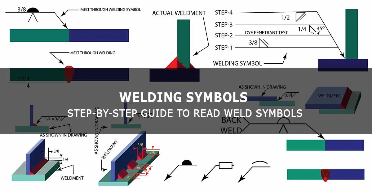
Welding Symbols Examples (What It Means To The Fabricator)
The illustrative images of fillet weld and groove weld discussed in the previous paragraphs show many examples of the welding symbols and what they mean to the fabricator. Each welding symbol shown in the said images consists of a single instruction step.
However, the designer can use the welding symbol with multiple reference lines connected to a single arrow to convey multiple steps to be followed by the fabricator in respect of the weld joint.
A welding symbol with multiple reference lines is explained in detail in the illustration shown below:

Differences Between AWS And ISO Standards For Welding Symbols
| Few important differences between AWS and ISO standards for welding symbols. | ||
| NO | AWS (American Welding Society) | ISO (International Standards Organization) |
| 01 | Mainly followed by the USA, Gulf countries, and a few Asian countries. | Mainly followed by European Union (EU), Australia, and a few Asian countries. The UK follows a similar system. |
| 02 | Has only one solid reference line.
The weld symbol placed below the reference line indicates the welding on the arrow side of the weld joint. The weld symbol placed above the reference line indicates the welding on the other side.
|
Has two reference (dual) lines, one is a solid reference line, and the other one is a dashed reference line.
The weld symbol placed on the solid reference line indicates the welding on the arrow side of the weld joint. The weld symbol placed on the dashed reference line indicates the welding on the other side. |
| 03 | The size of the filet weld is designated by its leg size. | The size of the filet weld is designated by its throat or leg size. |
| 04 | Dimensions are normally mentioned in inches and a fraction of an inch. | Dimensions are normally mentioned in millimeters. |
Conclusion
Weld symbols and welding symbols have a very important role in the fabrication industry since it helps clear communication between the technical staff in an engineering fabrication workshop. It is important for every technical person involved in the fabrication, be it a designer or a shopman, to understand and learn what the welding symbol on a fabrication drawing means so that the actual fabrication happens as visualized by the designer.
Hopefully, this article has given you a basic understanding of weld symbols and welding symbols. However, as a fabrication professional, you must purchase a copy of the relevant standard (AWS or ISO) and refer to it in your day-to-day work (because an article cannot cover everything in a standards book).